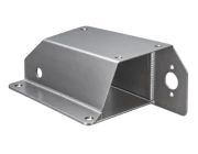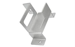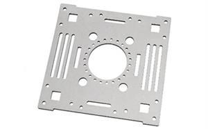

This guide is designed to help mechanical engineers and product designers optimize laser-cut and bent sheet metal parts for welding processes. By adhering to Design for Manufacturability (DFM) standards during the CAD modeling stage, you can significantly enhance structural strength, eliminate thermal distortion, reduce assembly tooling costs, and shorten production lead times.
1. Allowed and Recommended Weld Joint Types
To ensure the mechanical strength of weld joints and effectively control heat input, we recommend using the following two standardized joint configurations:
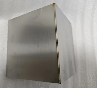
Corner Weld
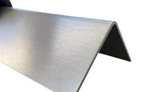
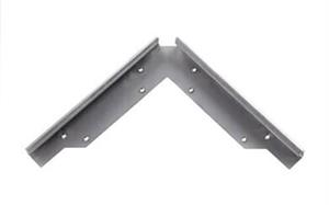
Two bent edges meet at a 90° right angle.
- Outside Corner Weld (Recommended): The welding torch is applied to the outside of the corner joint, yielding superior penetration, better fill, and a fuller weld appearance.
- Inside Corner Weld: The welding torch is applied to the inside concave corner, suitable for applications with external assembly interference where weld protrusions are not permitted.

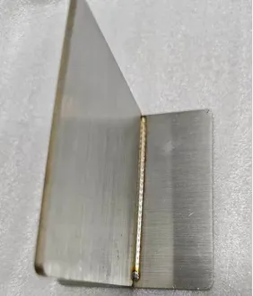
T-Joint Weld
One bent edge meets perpendicularly with the flat surface of another extending flange.
- Also divided into Inside Fillet Weld and Outside Fillet Weld.
- T-Joints offer excellent shear strength and are ideal for stiffeners, gussets, or baffle structures.
Unsupported Weld Types: Butt welds, lap welds, spot welds, stitch welds, and complex multi-part assembly welds are currently not available for standardized automated online quoting and processing, and require manual engineering review.
2. CAD Modeling & Design Rules
"Design for Bending First" Principle
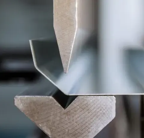
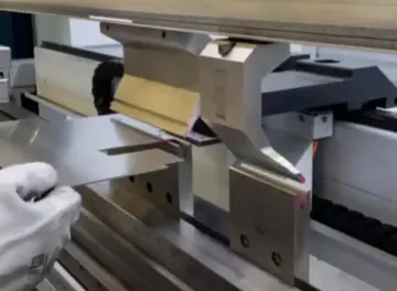
All welded parts must first satisfy standard sheet metal bending specifications. Design should complete 3D bend modeling first, as welding is a secondary process performed after bending. Always check clearance for bending tooling to prevent welding flanges from obstructing the bending stroke.
Do NOT Model Weld Geometry
Never draw fillet welds, weld beads, or weld cutouts in your CAD model. The model must reflect true, un-welded sheet metal bend geometry. The factory CAM system will automatically calculate weld compensation and joint normalization based on the selected material and thickness.
Bend Reliefs and Unsealed Corners
Laser welding is primarily used for structural connection and positioning alignment; it does not guarantee watertight or gastight seals. Bend relief gaps and open bend seams will not be automatically filled. If sealing is required, post-process sealant must be applied or manual full-fill grinding specified.
3. Innovative Features: Fixtureless Self-Alignment & Thermal Control Structures
To eliminate reliance on expensive welding fixtures and resolve thermal distortion issues in thin sheet metal welding, this guide introduces the following innovative DFM techniques:
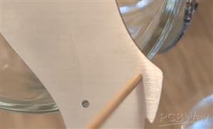
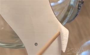
Tab-and-Slot Self-Alignment Design
Incorporate interlocking tabs and slots directly into mating parts during the laser cutting phase.
- Engineering Advantage: Parts achieve precise interlocking alignment without fixtures, eliminating cumulative assembly errors and manual measurement setup time.
- Design Rule: Tab width is recommended to be 3x to 5x the sheet thickness, with a unilateral clearance allowance of 0.1mm~0.15mm.
Integrated Locating Holes and Alignment Pins
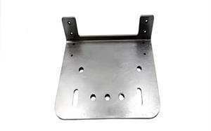
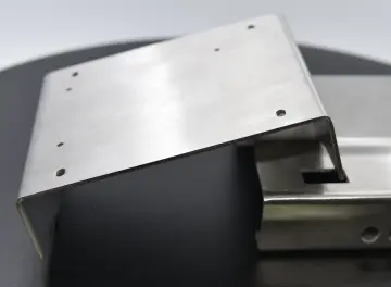
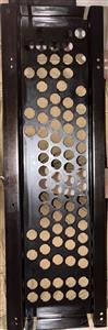
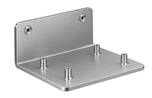
Place laser-cut locating holes(3.0mm~5.0mm)on non-welded datum surfaces to accept standard dowel/spring pins or locating bolts. This improves high-volume assembly consistency and serves as a inspection measurement datum.
Heat-Affected Zone (HAZ) Relief Cuts & Anti-Distortion Design
Thin sheet metal welding (e.g., 1.5mm aluminum alloy) is prone to "oil-canning" or wave distortion due to localized thermal expansion.
- Stress Relief Slots: Incorporate elongated stress-relief slots in non-load-bearing areas adjacent to the weld to block thermal stress propagation across large flat surfaces.
- Pulsed Laser Welding: Utilizing pulsed laser welding reduces the heat-affected zone to only 1/5 that of traditional TIG/MIG welding, drastically reducing residual stress while producing a visually appealing "stack-of-dimes" surface finish.
4. Finished Appearance, Delivery Expectations, and Post-Processing

5. Design Checklist
Please review and verify the following items prior to order submission or production release:
- CAD Model Specification: Correct bending parameters have been applied to the part model, and no 3D weld beads or fillets have been modeled.
- Root Gap: The assembly gap (root gap) at the target weld joint is controlled within 0.020'' (0.5mm) in CAD.
- Self-Alignment Features: Tab-and-slot features or locating holes have been prioritized to reduce assembly and fixture alignment difficulty.
- Torch Clearance: Weld locations avoid complex multi-bend intersections or tight internal enclosures, ensuring adequate torch accessibility and line of sight.
- Coating Allowance: If powder coating or anodizing is required later, coating thickness allowances have been factored into mating tolerances (e.g., adding 0.05~0.1mm per side for powder coat).