Prototipos de PCB de forma sencilla

Servicio completo para prototipos de PCB personalizados.

Centro de Ayuda
Enviando un mensaje
9:00 - 23:00, Mon.- Sun. (GMT+8)
Líneas directas de servicio
+86 571 8531 7532

9:00 - 18:00, Mon.- Fri. (GMT+8)

9:00 - 12:00, Sat. (GMT+8)

(Excepto los días festivos chinos públicos)


Plated Half-Holes(Castellated Holes)

Plated half-holes, also known as castellated holes, are similar to plated through-holes, but their shape is only half of a plated through-hole. Plated half-holes are used to solder individual circuit board modules onto other PCBs. For example, when PCB modules like Bluetooth or Wi-Fi need to be installed on another circuit board, plated half-holes are the preferred choice.

How to Design Plated Half-Holes?

When designing plated half-holes, please note the following points:

  • Place the center point of each plated half-hole precisely on the edge or outline of the PCB (for oval-shaped holes, pay attention to the start and end points).It is important to define these holes as plated through-holes in your EDA application.If you are uploading Gerber files,make sure to place the holes/slots in the drill file, such as *.drills_pth.xln file, *pth.drl file.

  • Each plated half-hole must be within a pad on each copper layer (including inner layers for a 4-layer board) to ensure sufficient stability of the copper sleeve.

  • Ensure that the pad fully surrounds the hole.The requirements for pads and annular rings are the same as for regular through-holes.

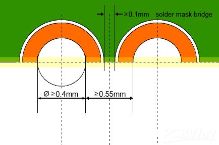
  • Minimum half-hole diameter:Typically,the minimum half-hole diameter is 0.6mm,but PCBWay accepts a minimum half-hole diameter of 0.4mm.

  • Minimum edge-to-edge spacing between holes:0.55mm.If it is between 0.47mm and 0.55mm,there will be an increase in price and lead time.

  • Minimum solder mask bridge size:0.1mm.

plated half holes.png

For specific details, please refer to the form below(Unit: MM)

PCB Thickness Castellated Hole LimitationCastellated Hole DiameterMinimum Size after Routing
≤1.00.40.40.25
1.2-1.60.4--0.60.25
0.7--0.90.35
≥1.00.45
20.4--0.60.25
0.7--0.80.4
≥0.90.45

By following the above guidelines, you can easily integrate plated half-holes into your PCB design. Please ensure that you use the correct parameters and dimensions during the design process, and communicate with PCB manufacturer promptly to ensure accurate manufacturing and assembly.

The Production Process of Plated Half-Holes

The traditional process for manufacturing plated half-holes typically involves the following steps: drilling - applying chemical copper to the panel - image transfer - pattern plating - film stripping - etching - solder mask layer printing - surface treatment - hole formation - contour milling.

However, the above steps can result in decreased productivity and performance of the product. Nowadays, the process of forming plated half-holes differs from the usual traditional methods.

The process of forming plated half-holes begins with drilling on the edge of the substrate. Therefore, it is crucial to use specialized drilling equipment as any deficiencies in the equipment can affect all subsequent steps. Once the preparation is completed, the next step is copper plating of the holes. Copper plating is equally essential as it ensures good conductivity for the components on the circuit board.

Advantages of Plated Half-Holes

Easy to handle and solder: Plated half-holes, located on the side of the module, are easily accessible. In contrast, having SMD pads on the bottom of the module can hinder component installation. To address this issue, plated half-holes are provided. Due to their edge positioning, soldering becomes much easier.

Easy to measure: When using plated half-holes, measuring the distance between the hole and the solder becomes easier. We can even use calipers to measure the distance, even after the module is placed. This would be impossible if the pads were beneath the module.

Coaxiality: When the pads are beneath the module, they can cause misalignment. However, when the holes are on the side of the PCB, the chances of alignment errors are reduced.

Cleaner board surface: PCB modules with plated half-holes are considered surface-mountable components. Hence, they can be directly mounted on another circuit board, just like SMD components. Therefore, the chances of dust and dirt accumulating between the two boards are minimal, as their connection is very tight.

Applications of Plated Half-Holes

  • Half-holes can be used as branch boards for specific sections of large PCBs.

  • These holes make it easier to modify the pin layout of components according to user requirements.

  • Integrated modules are produced using half-holes for connection on a single PCB and are further utilized during the assembly process.

  • During PCB assembly, PCBs with half-holes can be easily mounted onto another PCB.

  • They are used to connect two boards together for validating the quality of solder joints.

  • They are used for branch boards or small modules such as WiFi modules.

  • Plated half-holes also aid in creating wireless PCB-to-PCB connections.

More information please check:

PCB Instant Quote

Comentarios (5)
Este mensaje aquí es solo una sugerencia que complementa el contenido anterior y no para operaciones comerciales como pedidos. Si tiene alguna pregunta urgente o problemas con el pedido, comuníquese con su representante de ventas.
Solo puede subir 1 archivo en total. Cada archivo no se puede exceder los 2 MB. Admite JPG, JPEG, GIF, PNG, BMP
0 / 10000