In the manufacturing process of electronic devices, gold finger, as a unique pin interface, plays a crucial role. With its distinctive metal coating, gold finger is hailed as the aristocratic connection in the PCB field.
What is Gold Finger?
On computer memory modules and graphics cards, there is a row of golden-colored conductive contacts commonly referred to as "gold fingers." They resemble fingers in appearance and are also gold in color, hence the nickname "gold fingers." They can also be referred to as edge connectors.
Gold fingers are gold-plated connectors located at the edge of a PCB. They serve as connectors between the PCB and the motherboard, ensuring reliable transmission of signals or commands. In addition to providing connectivity, the gold plating also serves to protect the edges of the circuit board from damage.
Edge fingers and edge connectors are two concepts that are easily confused. Although both involve the connection of electronic devices, their purposes and functions are different.Next, we will explain the difference between them.
Edge connector
An edge connector is a specially designed connector used to mate with edge fingers. They are typically made of plastic or metal and feature slots or holes that are compatible with the edge fingers. The purpose of edge connectors is to connect electronic devices to other modules or external devices, enabling data transfer and electrical signal exchange. Common examples of edge connectors include expansion card slots, module sockets, and so on.
Comparison between Gold Fingers and Edge Connectors
Utility: Gold fingers are used to connect the PCB to peripheral devices or the motherboard, creating an interface for data transfer via USB and storage cards. While edge connectors are used in computers as expansion slots (to connect PCIe, PCI, and AGP cards to the system bus).
Placement: Gold fingers are located at the edge of the board, while edge connectors can be installed anywhere on the circuit board.
Package: Gold fingers are gold-plated for enhanced conductivity and durability. They can be plugged and unplugged as needed. While edge connectors are enclosed in a thermoplastic box, with one side of the box being open and the pins located along the edge.
Design: Gold fingers are designed as solder pads. They are created after the solder mask preparation and require additional milling to obtain chamfered edges. On the other hand, edge connectors are configured as pins that are inserted and soldered into through-holes.
Usage: Gold fingers are convenient in situations where frequent connection and disconnection are required. By repeatedly plugging and unplugging gold fingers, reliable electrical connections can be achieved without significant damage or wear to the connector or contact points. On the other hand, edge connectors are typically permanently fixed once inserted into the board and are not as easy to dismantle and replace.
Price: Gold fingers have higher manufacturing costs as they require gold plating. Conversely, edge connectors are cheaper as they are typically made of plastic or metal materials.
The Surface Treatment Methods for PCB Gold Fingers
Electroplated Nickel Gold: With a thickness ranging from 3-50µ", electroplated nickel gold is widely used for gold fingers on PCBs that require frequent plugging and unplugging or undergo mechanical friction. It offers excellent conductivity, oxidation resistance, and wear resistance. However, due to the high cost of gold plating, it is typically used for localized gold plating, such as gold fingers.
Immersion Gold: Typically with a thickness of 1µ", up to a maximum of 3µ", immersion gold is widely applied to high-precision PCBs with features like keypads, IC bonding, or BGA (Ball Grid Array). It provides superior conductivity, surface flatness, and solderability. For gold finger PCBs that do not require high wear resistance, full-board immersion gold can be chosen as a cost-effective alternative to electroplated gold. The color of immersion gold is golden yellow.
Category of Gold Fingers
Gold fingers can be divided into regular gold fingers (flush gold fingers), segmented gold fingers (intermittent gold fingers), and long-short gold fingers (uneven gold fingers).
Regular gold fingers (flush gold fingers): Rectangular solder pads with the same length and width are neatly arranged at the edge of the board. They are commonly used for physical connections in network cards, graphics cards, and similar devices.

Segmented gold fingers (intermittent gold fingers): Rectangular solder pads of different lengths located at the edge of the circuit board, with a front section disconnected.

Long-short gold fingers (uneven gold fingers): Rectangular solder pads of varying lengths located at the edge of the board. They are commonly used for physical connections in devices such as memory modules, USB drives, and card readers.

Design Rules for Gold Fingers
There should be a minimum distance of 0.5mm between the gold fingers and the PCB board outline.

No SMD components, plated holes, or solder pads are allowed within a 1mm range of the gold fingers.
All inner layers within the gold fingers must undergo copper removal to prevent copper exposure during chamfering. Typically, the width of copper removal should be greater than 3mm. It can be done as half-finger copper removal or full-finger copper removal. In PCIE designs, there are indications that all copper within the gold fingers should be removed. Copper removal beneath the fingers can reduce the impedance mismatch between the gold fingers and impedance-controlled traces, providing benefits for ESD protection.
The length of all gold fingers should not exceed 40mm.
Avoid soldermask or silkscreen printing near the gold fingers.
To enhance the wear resistance of gold fingers, they are typically hard gold plated.
During PCB design, the gold fingers must have a continuous solder mask opening, and no steel mesh is required for the pins.
Gold fingers must be designed with chamfers, typically at a 45° angle. Other angles such as 20° or 30° can be chosen. The absence of chamfers in the PCB design of gold fingers indicates a problem. In the image below, the arrow indicates a 45° chamfer.

The surface of the gold fingers should avoid copper plating.
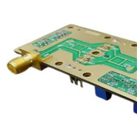
The following image shows a design example of gold fingers for reference.

PCBWay Commonly Used Gold Finger Chamfer Parameters
Edge chamfer is the process of creating a transitional edge between the two surfaces of a circuit board, usually done on the outer edge of the board. The chamfer allows the gold fingers to smoothly insert into edge connectors of other PCBs. PCBWay commonly used gold finger chamfer parameters are shown in the table below:
| Commonly used gold finger chamfer parameters |
| Angle(α) | PCB thickness(d) | Remaining thickness(s) | Chamfer depth(h) |
| 20° | 1.6mm | 0.5mm | 1.51mm |
| 2.0mm | 0.65mm | 1.85mm |
| 2.4mm | 0.7mm | 2.34mm |
| 30° | 1.6mm | 0.5mm | 0.95mm |
| 2.0mm | 0.65mm | 1.16mm |
| 2.4mm | 0.7mm | 1.47mm |
| 45° | 1.6mm | 0.5mm | 0.5mm |
| 2.0mm | 0.65mm | 0.65mm |
| 2.4mm | 0.7mm | 0.7mm |

Note: PCBWay can also produce gold fingers with a chamfer angle of 60°.
Gold finger chamfer angle tolerance: +/- 5°.
Gold finger chamfer height tolerance: +/- 5 mil.
More information please check here:
PCB Instant Quote