Prototipos de PCB de forma sencilla
Servicio completo para prototipos de PCB personalizados.
9:00 - 18:00, Mon.- Fri. (GMT+8)
9:00 - 12:00, Sat. (GMT+8)
(Excepto los días festivos chinos públicos)
ISO 2768 is an international standard published by the International Organization for Standardization (ISO) that specifies general tolerances for mechanical engineering drawings. It is widely used in CNC machining, sheet metal fabrication, welded structures, and other manufacturing processes. By defining default tolerances for unspecified dimensions and geometrical features, ISO 2768 helps ensure manufacturing quality while simplifying engineering drawings and improving communication among design, manufacturing, and inspection teams.
ISO 2768 consists of two parts: ISO 2768-1 and ISO 2768-2.
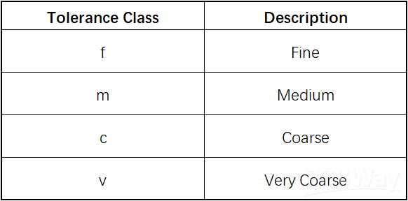
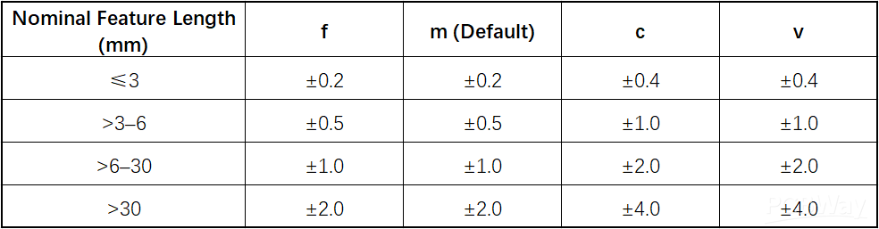
This part specifies general tolerances for part dimensions, including lengths, widths, diameters, step dimensions, chamfers, radii, and angles. It defines four tolerance classes:

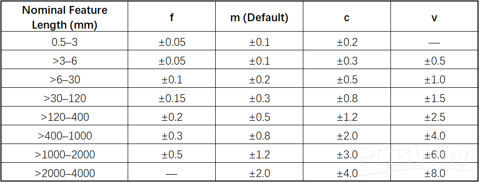
Permissible deviations for linear dimensions such as length, width, height, diameter, and thickness.

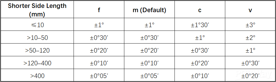
Permissible deviations for angular dimensions. The tolerance depends on the length of the shorter side of the angle.

Permissible deviations for radii (R) and chamfer dimensions (C).

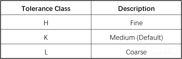
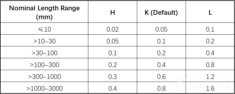
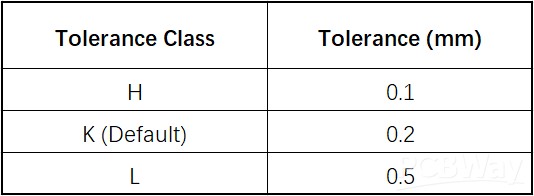
This part specifies general tolerances for the form and location of features, including straightness, flatness, perpendicularity, symmetry, and circular run-out. It defines three tolerance classes:

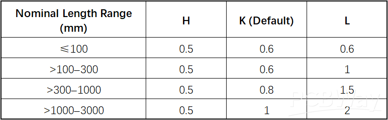
Maximum permissible deviation of a line or surface from its theoretically perfect straight or flat condition.

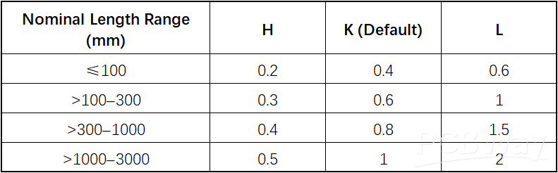
Maximum permissible deviation of a feature from a theoretically perfect 90° orientation relative to a datum plane or datum axis.

Maximum permissible deviation of a feature from its theoretically symmetrical position relative to a datum plane or datum axis.

Controls the maximum radial variation of a rotating feature during one complete revolution about its datum axis to ensure rotational accuracy.

In practice, the two parts are typically used together. For example, a drawing marked ISO 2768-mK indicates that general dimensional tolerances follow Class m of ISO 2768-1, while general geometrical tolerances follow Class K of ISO 2768-2. This specification is commonly applied to general machining and sheet metal components.
• ISO 2768 applies only to dimensions and geometrical features for which no individual tolerances are specified.
• Where a drawing explicitly specifies a tolerance, the specified tolerance takes precedence over the general tolerance.
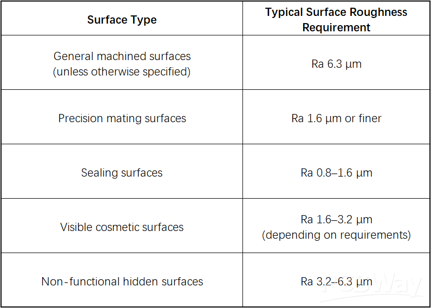
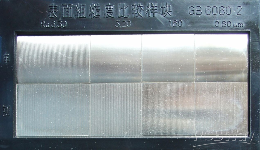
• ISO 2768 does not define surface roughness requirements. Surface roughness values (such as Ra 3.2 μm or Ra 1.6 μm) shall be specified separately in accordance with the drawing or applicable standards.
• For mating dimensions, critical functional dimensions, or high-precision components, individual tolerances should be specified to ensure proper assembly and product reliability.
Unless otherwise specified, the default surface roughness is Ra 6.3 μm. For more information about CNC machining surface roughness and how different Ra values affect part appearance and performance, see our guide on CNC machining surface roughness.


PCBWay offers custom fabrication and manufacturing services tailored to your specific size and tolerance requirements.
If you have any questions, please feel free to contact our professional engineers at any time for expert consultation.