


|
Arduino Nano IoT 33Arduino
|
x 1 | |
|
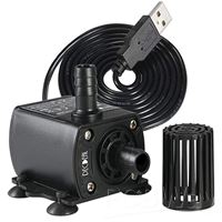
Submersible Water PumpDecdeal
|
x 1 | |

|
LEDS1E-8-01Essentra
|
x 1 |

|
arduino IDEArduino
|
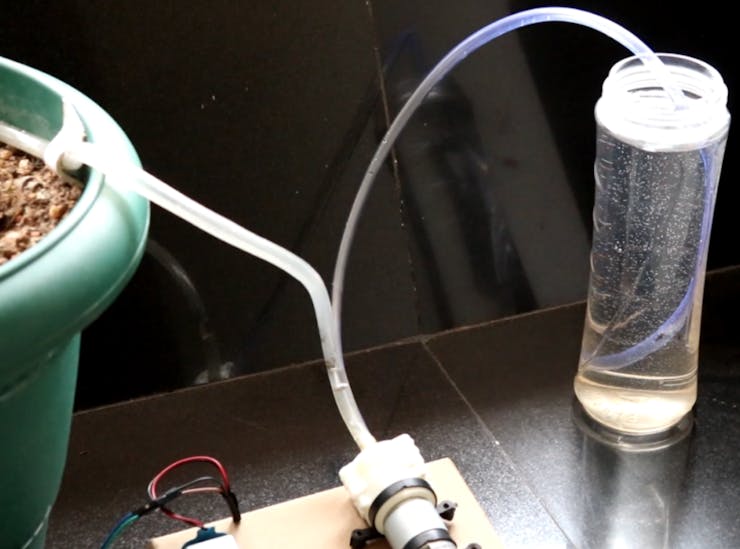
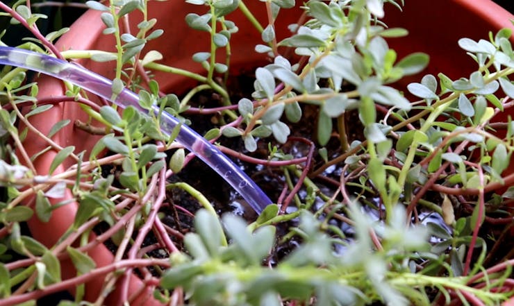
Lets make an IOT based plant watering system using Arduino Nano 33 IoT, some pumps and an Android Smart Phone.
Introduction
Home automation is a popular subject these days and with excellent cause. Our smart devices may be connected to the Internet and controlled remotely using an app or voice software. This implies that you won’t have to manually control them anymore when you want to adjust the thermostat, draw the curtains, or water your plants!
Advantages of IoT enabled Plant Watering System
One of the main benefits of using a smart irrigation system is that it can help conserve water. By watering plants at regular intervals, we can prevent them from becoming dehydrated and save valuable resources in the process. A well-watered plant is a healthy plant, and an IoT-enabled watering system can help ensure that your plants are getting the right amount of water at all times. This is especially important for outdoor plants that might not get regular attention.
Perhaps the nicest part about utilizing an IoT-enabled irrigation system is that you can control it from anywhere if you have a connection to the internet. This means we may reap the benefits of this plant watering timer without having to water the plants manually before leaving for work on certain days, allowing us to focus on other tasks!
Circuit
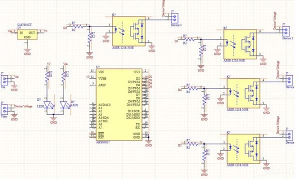
So I used Altium Designer to draw the circuit and design the PCB. It is a powerful tool that can be used to design and create your own PCBs for your project as well as complex and multiplayer PCBs for industrial use. I will leave the link to the free trial version in the description.
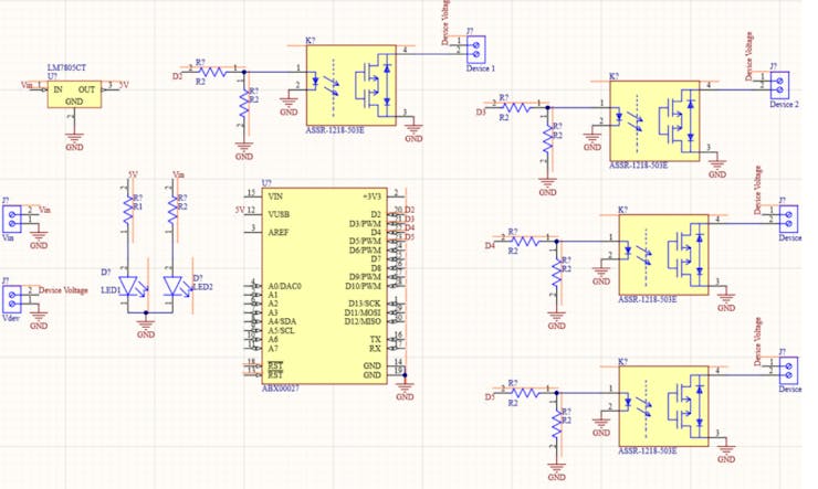
Also, if you are planning to buy it, there is an awesome 30% discount by purchasing it using the link below! So do make use of it!The board has two voltage inputs: one for the Arduino and other components, and another for driving the electronic devices connected to the relay, which will be controlled by an Android App.
Here, I’ll be connecting a 12 V DC adapter to power the Pumps.
A 7805 regulator is used to regulate the input voltage. The 7805 is a 5V regulator that converts an input voltage of 7-32V to a consistent 5V DC supply by using a 7-32V adjustable voltage conversion.
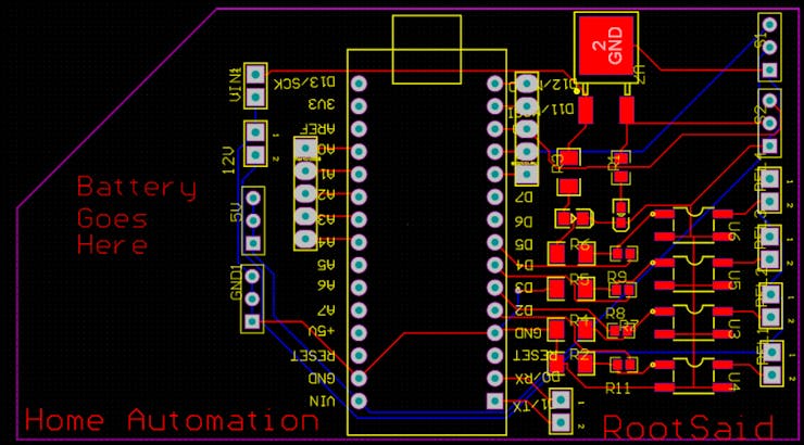
After the circuit was created and tested, I drew up a PCB layout for our watering system so I can simply mount your Arduino Nano 33 IOT and SSR, connect everything without having wires or cables hanging around. The board is compact and lightweight, and it may be run on a 9V battery or a 9-12 V power adapter.
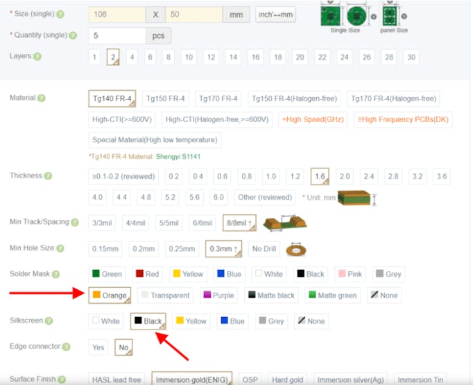
Getting PCB Done
I ordered PCB from PCBWay. PCBWay is a PCB manufacturer specializing in PCB prototyping, low-volume production, and neat and tidy PCB assembly.

To order your PCB from PCBWay, go to the PCBWay website and fill in the basic board details in the instant order form. From there you will be directed to a form where you can provide more elaborate board details. Update your board information in the PCB specification screen. On the next screen, you should be able to upload your Gerber file and submit it for review. Once the review is completed, all that is left is to add to the cart, make payment, and wait for your PCBs to arrive.
Once you get all the components and the PCB, it’s time for you to solder them together. Solder all the components onto the board and make sure to check the polarity of the components. After soldering the PCB looks like this.
I personally find soldering on this kind of PCBs a fun task, because of these pads soldering becomes very easy. The solder takes up the conical shape and gets soldered from all the sides evenly. After soldering the PCB looks like this.
Step 2 – Download, Install, and Setup Arduino IDE
This tiny board may be readily programmed using the most user-friendly Open Source Platform – Arduino. This will be discussed in further detail. So, to start with, download and install the Arduino IDE from Here
Code
Let’s Take a look at the code –
#include <SPI.h>
#include <WiFiNINA.h>
#include <WiFiUdp.h>

int status = WL_IDLE_STATUS;
#include "arduino_secrets.h"
char ssid[] = SECRET_SSID;
char pass[] = SECRET_PASS;
int keyIndex = 0;
unsigned int localPort = 5005;

char packetBuffer[256];
char  ReplyBuffer[] = "acknowledged";

WiFiUDP Udp;

void setup() {
    pinMode(3, OUTPUT);
    pinMode(4, OUTPUT);
    pinMode(5, OUTPUT);
    pinMode(6, OUTPUT);
  Serial.begin(9600);
  while (!Serial) {
    ;
  }

  // check for the WiFi module:if (WiFi.status() == WL_NO_MODULE) {
    Serial.println("Communication with WiFi module failed!");
    // don't continuewhile (true);
  }

  String fv = WiFi.firmwareVersion();
  if (fv < WIFI_FIRMWARE_LATEST_VERSION) {
    Serial.println("Please upgrade the firmware");
  }

  // attempt to connect to Wifi network:while (status != WL_CONNECTED) {
    Serial.print("Attempting to connect to SSID: ");
    Serial.println(ssid);
    status = WiFi.begin(ssid, pass);

    delay(10000);
  }
  Serial.println("Connected to wifi");
  printWifiStatus();

  Serial.println("nStarting connection to server...");
  Udp.begin(localPort);
}

void loop() {

  int packetSize = Udp.parsePacket();
  if (packetSize) {
    //Serial.print("Received packet of size ");//Serial.println(packetSize);//Serial.print("From ");
    IPAddress remoteIp = Udp.remoteIP();
   // Serial.print(remoteIp);// Serial.print(", port ");// Serial.println(Udp.remotePort());

    int len = Udp.read(packetBuffer, 255);
    if (len > 0) {
      packetBuffer[len] = 0;
    }
    Serial.print("Command Received: ");
    Serial.println(packetBuffer);


 if(strcmp(packetBuffer, "device1on") == 0)
    {
       digitalWrite(3, HIGH);
       Serial.println("Turning Device 1 ON");

    }
 else if(strcmp(packetBuffer, "device1off") == 0)
    {
       digitalWrite(3, LOW);
       Serial.println("Turning Device 1 OFF");
    }
 else if(strcmp(packetBuffer, "device12on") == 0)
    {
       digitalWrite(4, HIGH);
       Serial.println("Turning Device 2 ON");
    }
 else if(strcmp(packetBuffer, "device2off") == 0)
    {
       digitalWrite(4, LOW);
       Serial.println("Turning Device 2 OFF");
    }
else if(strcmp(packetBuffer, "device3on") == 0)    {
       digitalWrite(5, HIGH);
       Serial.println("Turning Device 3 ON");
    }
else if(strcmp(packetBuffer, "device3off") == 0)    {
       digitalWrite(5, LOW);
       Serial.println("Turning Device 3 OFF");
    }
else if(strcmp(packetBuffer, "device4on") == 0)    {
       digitalWrite(6, HIGH);
       Serial.println("Turning Device 4 ON");
    }
else if(strcmp(packetBuffer, "device4off") == 0)    {
       digitalWrite(7, LOW);
       Serial.println("Turning Device 4 OFF");
    }

Serial.println("");
    Udp.beginPacket(Udp.remoteIP(), Udp.remotePort());
    Udp.write(ReplyBuffer);
    Udp.endPacket();
  }
}

void printWifiStatus() {
  // print the SSID of the network you're attached to:
  Serial.print("SSID: ");
  Serial.println(WiFi.SSID());

  // print your board's IP address:
  IPAddress ip = WiFi.localIP();
  Serial.print("IP Address: ");
  Serial.println(ip);

  // print the received signal strength:long rssi = WiFi.RSSI();
  Serial.print("signal strength (RSSI):");
  Serial.print(rssi);
  Serial.println(" dBm");
}
This is where you enter the ESSID and Passphrase of your network. Before uploading, make sure that you change values to SSID and Passphrase of your WiFi network.
This is the port, Arduino will be listening for incoming UDP packets, The 4 pins we will connect to the relay input, Here, we will connect to the WiFi network using predefined ESSID and Passphrase and set up a UDP listener in the predefined port, Save the UDP packet contents to the variable ‘packetBuffer’ and print its value. Turns the output of the pins to HIGH or LOW depending upon the packets received.
App
RootSaid WiFi Command Center is a simple lightweight android application that can be used to control robots and home devices using Raspberry Pi and Arduino over WiFi. All you have to do is connect your mobile phone to the network, enter the IP address and port of the server (the Arduino of our Home Automation system using Arduino) and control it using the On-Off buttons. Click here to know more about this App. Click Here to Download this app from Playstore.
Testing!
Now all you have to do is start the app, enter the IP address of the Arduino and port it is listening to (5005). Load the IP and Port using the link button and navigate to the Home Automation Tab. Now, you should be able to turn on and off different pumps using the buttons.
You can now use this simple project to control pumps connected to your Arduino and turn it on and off.
#include <SPI.h>
#include <WiFiNINA.h>
#include <WiFiUdp.h>

int status = WL_IDLE_STATUS;
#include "arduino_secrets.h"
char ssid[] = SECRET_SSID;
char pass[] = SECRET_PASS;
int keyIndex = 0;
unsigned int localPort = 5005;

char packetBuffer[256];
char  ReplyBuffer[] = "acknowledged";

WiFiUDP Udp;

void setup() {
    pinMode(3, OUTPUT);
    pinMode(4, OUTPUT);
    pinMode(5, OUTPUT);
    pinMode(6, OUTPUT);
  Serial.begin(9600);
  while (!Serial) {
    ;
  }

  // check for the WiFi module:
  if (WiFi.status() == WL_NO_MODULE) {
    Serial.println("Communication with WiFi module failed!");
    // don't continue
    while (true);
  }

  String fv = WiFi.firmwareVersion();
  if (fv < WIFI_FIRMWARE_LATEST_VERSION) {
    Serial.println("Please upgrade the firmware");
  }

  // attempt to connect to Wifi network:
  while (status != WL_CONNECTED) {
    Serial.print("Attempting to connect to SSID: ");
    Serial.println(ssid);
    status = WiFi.begin(ssid, pass);

    delay(10000);
  }
  Serial.println("Connected to wifi");
  printWifiStatus();

  Serial.println("nStarting connection to server...");
  Udp.begin(localPort);
}

void loop() {

  int packetSize = Udp.parsePacket();
  if (packetSize) {
    //Serial.print("Received packet of size ");
    //Serial.println(packetSize);
    //Serial.print("From ");
    IPAddress remoteIp = Udp.remoteIP();
   // Serial.print(remoteIp);
   // Serial.print(", port ");
   // Serial.println(Udp.remotePort());

    int len = Udp.read(packetBuffer, 255);
    if (len > 0) {
      packetBuffer[len] = 0;
    }
    Serial.print("Command Received: ");
    Serial.println(packetBuffer);


 if(strcmp(packetBuffer, "device1on") == 0)
    {
       digitalWrite(3, HIGH);
       Serial.println("Turning Device 1 ON");

    }
 else if(strcmp(packetBuffer, "device1off") == 0)
    {
       digitalWrite(3, LOW);
       Serial.println("Turning Device 1 OFF");
    }
 else if(strcmp(packetBuffer, "device12on") == 0)
    {
       digitalWrite(4, HIGH);
       Serial.println("Turning Device 2 ON");
    }
 else if(strcmp(packetBuffer, "device2off") == 0)
    {
       digitalWrite(4, LOW);
       Serial.println("Turning Device 2 OFF");
    }
else if(strcmp(packetBuffer, "device3on") == 0)    {
       digitalWrite(5, HIGH);
       Serial.println("Turning Device 3 ON");
    }
else if(strcmp(packetBuffer, "device3off") == 0)    {
       digitalWrite(5, LOW);
       Serial.println("Turning Device 3 OFF");
    }
else if(strcmp(packetBuffer, "device4on") == 0)    {
       digitalWrite(6, HIGH);
       Serial.println("Turning Device 4 ON");
    }
else if(strcmp(packetBuffer, "device4off") == 0)    {
       digitalWrite(7, LOW);
       Serial.println("Turning Device 4 OFF");
    }

Serial.println("");
    Udp.beginPacket(Udp.remoteIP(), Udp.remotePort());
    Udp.write(ReplyBuffer);
    Udp.endPacket();
  }
}

void printWifiStatus() {
  // print the SSID of the network you're attached to:
  Serial.print("SSID: ");
  Serial.println(WiFi.SSID());

  // print your board's IP address:
  IPAddress ip = WiFi.localIP();
  Serial.print("IP Address: ");
  Serial.println(ip);

  // print the received signal strength:
  long rssi = WiFi.RSSI();
  Serial.print("signal strength (RSSI):");
  Serial.print(rssi);
  Serial.println(" dBm");
}
Lets make an IOT based plant watering system using Arduino Nano 33 IoT, some pumps and an Android Smart Phone.


- Comments(0)
- Likes(1)
 More by Krishna S
-
 DIY Home Automation using Arduino UNO R4
Welcome to this beginner's guide to making your own home automation system, leveraging the prowess o...
DIY Home Automation using Arduino UNO R4
Welcome to this beginner's guide to making your own home automation system, leveraging the prowess o...
-
 Getting Plants Watered Automatically: A Guide to Scheduling
In this guide, we'll explore how using a scheduler in your DIY electronic projects can automate your...
Getting Plants Watered Automatically: A Guide to Scheduling
In this guide, we'll explore how using a scheduler in your DIY electronic projects can automate your...
-
 DIY Motion Triggered Halloween Prop using Arduino/Digispark
Having Halloween decorations that come to life is absolutely fun. Unfortunately, there are significa...
DIY Motion Triggered Halloween Prop using Arduino/Digispark
Having Halloween decorations that come to life is absolutely fun. Unfortunately, there are significa...
-
 Control your Home Devices using Arduino and Personal Assistant
IntroductionIn the previous video, we build an Alexa-controlled Door Locking System. So many people ...
Control your Home Devices using Arduino and Personal Assistant
IntroductionIn the previous video, we build an Alexa-controlled Door Locking System. So many people ...
-
 Making A Gesture Controller Glove using Hall Effect Sensor
StoryHey guys, in this video, we will be making a compact circuit that can be fitted in a glove to c...
Making A Gesture Controller Glove using Hall Effect Sensor
StoryHey guys, in this video, we will be making a compact circuit that can be fitted in a glove to c...
-
 Voice Controlled Door Lock using Alexa and Arduino
Voice Controlled Door Lock: An OverviewHey, everyone! Welcome back. In this video, we'll make an Ale...
Voice Controlled Door Lock using Alexa and Arduino
Voice Controlled Door Lock: An OverviewHey, everyone! Welcome back. In this video, we'll make an Ale...
-
 Making a DIY Soldering Fume Extractor with Lighting
IntroductionSoldering is awesome, right? It's fun to make our own PCB for our project, but there are...
Making a DIY Soldering Fume Extractor with Lighting
IntroductionSoldering is awesome, right? It's fun to make our own PCB for our project, but there are...
-
 Driving 4 High Current Motors in your Robot using a Simple L293D Piggy Backed Arduino Nano Shield
StoryHey, guys welcome back, In this post, I will show you how you can make your own high current mo...
Driving 4 High Current Motors in your Robot using a Simple L293D Piggy Backed Arduino Nano Shield
StoryHey, guys welcome back, In this post, I will show you how you can make your own high current mo...
-
 USB Joystick using Arduino for Robotics and Computer Game
Hey guys, in this video, we are going to make an amazing compact joystick using Arduino. We can use ...
USB Joystick using Arduino for Robotics and Computer Game
Hey guys, in this video, we are going to make an amazing compact joystick using Arduino. We can use ...
-
 How to make an Arduino UNO at Home? DIY Arduino
In this project, we are going to be making our own customized Arduino Uno board and I will be showin...
How to make an Arduino UNO at Home? DIY Arduino
In this project, we are going to be making our own customized Arduino Uno board and I will be showin...
-
 Beating Heart PCB for Valentines Day | Love is in the Circuit
Hey guys it’s valentine’s day! So let me ask you a question. what gift are you going to give to your...
Beating Heart PCB for Valentines Day | Love is in the Circuit
Hey guys it’s valentine’s day! So let me ask you a question. what gift are you going to give to your...
-
 5V – 3.3V Logic Level Shifter IC for Arduino and Raspberry Pi
Hey, Guys welcome back to RootSaid. In ...
5V – 3.3V Logic Level Shifter IC for Arduino and Raspberry Pi
5V – 3.3V Logic Level Shifter IC for Arduino and Raspberry PiHey, Guys welcome back to RootSaid. In ...
-
 Lets make an IOT based plant watering system using Arduino Nano 33 IoT, some pumps and an Android Smart Phone.
IntroductionHome automation is a popular subject these days and with excellent cause. Our smart devi...
Lets make an IOT based plant watering system using Arduino Nano 33 IoT, some pumps and an Android Smart Phone.
IntroductionHome automation is a popular subject these days and with excellent cause. Our smart devi...
-
 DIY Photoshop Editing Console using Arduino Nano RP 2040
Making a DIY Photoshop Editing ConsoleWhat if there was something that we could use to quickly chang...
DIY Photoshop Editing Console using Arduino Nano RP 2040
Making a DIY Photoshop Editing ConsoleWhat if there was something that we could use to quickly chang...
-
 DIY Halloween Pumpkin using Arduino
It’s time to get ready for Halloween! We’re going to be doing a lot of DIY stuff this month, so stay...
DIY Halloween Pumpkin using Arduino
It’s time to get ready for Halloween! We’re going to be doing a lot of DIY stuff this month, so stay...
-
 Drink Like James Bond! DIY Cocktail Mixer Using Arduino
Robotic BartenderThis weekend you can make your next cocktail party an even bigger success by buildi...
Drink Like James Bond! DIY Cocktail Mixer Using Arduino
Robotic BartenderThis weekend you can make your next cocktail party an even bigger success by buildi...
-
-
Open Source Very Large Stick - Freejoy & MMjoy2 breakout board
524 0 0 -
RF Control training board for students based on ESP32 C3
706 0 2 -
-
KINETIC COASTERS with a TWIST! Laser or 3D Print some DIY Magic
620 0 1 -
RPI - 8 IO PLC With ATTiny85 Watch Dog
542 0 1 -
Nintendo Famicom HVC-001 Controller Shells
643 0 1 -
COMMODORE 128 DIAGNOSTIC REV.785260 KEYBOARD DONGLE
602 0 4 -
COMMODORE 128 15KHz DISPLAY ADAPTER (C128 80 COLUMN ADAPTER)
821 1 7


