


|
arduino IDEArduino
|
|

|
KiCADKicad
|
Large 1.8" + 0.8" 6 digit LED clock using ATMega328P and TPIC6B595 shift registers
The story
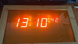
I recently bought a few LED displays as a job lot which were parts for fruit machines; the type you see in the local pub and after testing them I found that they had a nice bright red / orange colour to them and decided to use them for a large clock project. As I have not made anything for a while and had some spare time on my hands (no pun intended) I thought I’d need to brush up on my PCB design skills and C++ coding skills. Hence this project was designed and built.
The clock
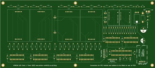
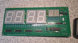
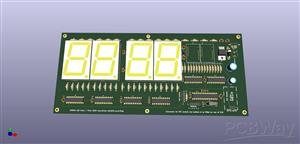
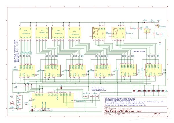
This is a large LED clock which uses 1.8″ high digits for the hours and minutes and the seconds is displayed on 0.8″ 7 segment displays. It is controlled by an ATMEGA168P or ATMEGA328P microcontroller and uses TPIC6B595 shift registers to drive the common anode displays. A DS3231 high precision RTC completes the electronics.
It is a large PCB measuring 270x120mm and can easily be seen from 30 feet away making it suitable for large workplaces or people with limited vision. The clock is powered from a 12V regulated power supply which can supply 800mA or more. A fuse and reverse polarity protection diode helps to prevent incorrect power supply connection from damaging the components. Finally three buttons are used for setting the time. There is provision on the PCB for a 4th button which could be used for something else if I wanted to add extra features later or with the code being open source you could make use of it yourself should you make one.
The clock does not have an alarm but features auto dimming at night between the hours of 11pm and 7am. Time is set by pressing the set button which makes the display show "SEt" and the seconds display will go blank. Use the hour set and minute set buttons to set the time and finally press set button again which will also zero the seconds. This way the clock can be synchronized to an accurate time source. A battery backed real time clock ensures it will keep going even if the power goes off.
This is an ideal basic project for beginners and demonstrates how shift registers work and the code used to make them drive LED displays. I will release the Gerber files and code so you can modify this project if you wish or use it as a learning tool which has a useful purpose. I will list some of these on eBay and / or Tindie in the coming weeks - please see my blog for details.
Libraries were used in the code which are linked / credited below.
This project was kindly sponsored by PCBWay who provided the version 1.1 PCB's with black soldermask.
Addendum to schematic - the 330ohm resistors should, ideally be replaced with 390ohm resistors instead as there is about 3mA segment current between the hours, mins segments and the seconds segments. This doesn't produce a noticeable difference with the displays I used but with some displays the seconds may appear dimmer than the rest. To avoid this substitute the 330 ohm resistors with 390 ohm resistors as this will bring the segment current within 1mA. Do not reduce the value of the seconds resistors from what is shown as this will increase the power dissipation resulting in them becoming too hot.
Links and videos etc
Button library by Alexander Brevig (GitHub page seems to be deleted) but fork here
// 6 Digit clock using TPIC6B595 shift registers
// Leftmost digit is digit 0
// Data will be fed in to the rightmost register first so digit 0 needs shifting out first.
// The clock will have 3 buttons - hour set, min set and enter / exit set mode.
// To set the time press the set button and the clock will go to the set time function - this is detected in main loop.
// To exit time set function press set button again, this will also zero the seconds and write new values to the rtc.
// A 4th button could be used to display temperature - not sure about this yet.

// 7-segment digits 0-9
// {Q0, Q1, Q2, Q3, Q4, Q5, Q6, Q7} --> {g, f, e, d, c, b, a, DP}

#include <SPI.h>
#include <SoftPWM.h>
#include <Wire.h>
#include <RTClib.h>
#include "Button.h"  // Button library by Alexander Brevig

const int reg_clock = 13; // SRCK
const int reg_latch = 10; // RCLK
const int reg_data = 11; // SER_IN
const int reg_OE = 9; // output enable; Active LOW. Can be used to control brightness with PWM.
const int colon_pin = 8; // used to dim the colon LED's when night mode enabled.

Button button1 = Button(2,BUTTON_PULLUP_INTERNAL);       // Setup button A (using button library)
Button button2 = Button(3,BUTTON_PULLUP_INTERNAL);       // Setup button B (using button library)
Button button3 = Button(4,BUTTON_PULLUP_INTERNAL);       // Setup button A (using button library)
Button button4 = Button(5,BUTTON_PULLUP_INTERNAL);       // Setup button B (using button library)

int brightness = 4; // set display brightness. Values 1-5. Set to level 4 as LED's I chose were eye searingly bright at level 5.
int brt = 0; // value for storing reversed PWM percentage
int set_mode = 0; // value for storing timeset mode true or false

#define DS3231_I2C_ADDR 0x68
#define DS3231_TEMPERATURE_ADDR 0x11

RTC_DS3231 rtc;

byte ssddigits[10] = // array without decimal points on
{
  B01111110,  // 0
  B00001100,  // 1
  B10110110,  // 2
  B10011110,  // 3
  B11001100,  // 4
  B11011010,  // 5
  B11111010,  // 6
  B01001110,  // 7
  B11111110,  // 8
  B11011110,  // 9
};

byte ssddigitsDP[10] = // array with decimal points on
{
  B01111111,  // 0
  B00001101,  // 1
  B10110111,  // 2
  B10011111,  // 3
  B11001101,  // 4
  B11011011,  // 5
  B11111011,  // 6
  B01001111,  // 7
  B11111111,  // 8
  B11011111,  // 9
};

byte tempC[2] = // C and degrees symbol
{
  B01110010,
  B11000110,
};

void setup() // runs once at powerup
{

  pinMode (reg_clock, OUTPUT);
  pinMode (reg_latch, OUTPUT);
  pinMode (reg_data, OUTPUT);
  pinMode (reg_OE,OUTPUT);
  pinMode (colon_pin, OUTPUT);
  digitalWrite(reg_OE,LOW); // enable output of shift register chain; an external pullup resistor on the OE pin prevents garbage being displayed at power on.
  digitalWrite(colon_pin, HIGH); // set colons to bright initially
  setBrt();
  SoftPWMBegin();
  SoftPWMSet(9, 0); // init software PWM on pin 9. This pulses the OE pin on and off to control brightness.
  SoftPWMSetPercent(9, brt);
  Wire.begin(); // start i2c
  rtc.begin(); //start RTC Clock
  set_mode = 0; // set timeset mode to off

  //rtc.adjust(DateTime(F(__DATE__), F(__TIME__))); // comment out once clock is initialy set

}

void loop() // main program loop
{
   if (set_mode == 1)

   {
     setTime();
   }

   else
   {
     clockDisplay();
   }

   if (button1.uniquePress())
   {
    SPI.beginTransaction(SPISettings(8000000, LSBFIRST, SPI_MODE0)); // display "set" for 2 seconds
    digitalWrite(reg_latch,LOW);
    SPI.transfer(B11011010); // S
    SPI.transfer(B11110010); // E
    SPI.transfer(B11110000); // t
    SPI.transfer(B00000000); // blank digit 3
    SPI.transfer(B00000000); // blank seconds display 10s
    SPI.transfer(B00000000); // blank seconds display 1s
    digitalWrite(reg_latch,HIGH);
    SPI.endTransaction();
    delay(2000);
    set_mode = 1; // enter timeset mode
   }

  setBrt();
  SoftPWMSetPercent(9, brt);
}

/// functions ///

void clockDisplay() // gets the time from the rtc and sends data to the shift registers.
{

  DateTime now = rtc.now();

  int hours = now.hour();
	int minutes = now.minute();
  int seconds = now.second();

  int h1, h2, m1, m2, s1, s2; // split the numbers into seperate digits using mod math
	h2 = hours % 10;
	h1 = ((hours % 100) - h1) / 10;
	m2 = minutes % 10;
	m1 = ((minutes % 100) - m1) / 10;
  s2 = seconds % 10;
  s1 = ((seconds % 100) - s1) / 10;

  // get digit 0
  int dig0 = (h1); // 10h
  // get digit 1
  int dig1 = (h2); // 1h
  // get digit 2
  int dig2 = (m1); // 10m
  // get digit 3
  int dig3 = (m2); // 1m
  // get digit 4
  int dig4 = (s1); // 10s
  // get digit 5
  int dig5 = (s2); // 1s

  SPI.beginTransaction(SPISettings(8000000, LSBFIRST, SPI_MODE0)); // send data to shift registers
  digitalWrite(reg_latch,LOW);
  SPI.transfer(ssddigits[dig0]);
  SPI.transfer(ssddigits[dig1]);
  SPI.transfer(ssddigits[dig2]);
  SPI.transfer(ssddigits[dig3]);
  SPI.transfer(ssddigits[dig4]);
  SPI.transfer(ssddigits[dig5]);
  digitalWrite(reg_latch,HIGH);
  SPI.endTransaction();

 if (now.hour() == 23 && now.minute() == 0 && now.second() == 0) // dim display at 23:00
    {
       brightness = 1;
       digitalWrite(colon_pin, LOW); // set colon to dim
    }

    if (now.hour() == 7 && now.minute() == 0 && now.second() == 0) // resume normal brightness at 7:00
    {
       brightness = 4;
       digitalWrite(colon_pin, HIGH); // set colon to bright.
    }

}

void setTime() // this will run if hour or minute set button is pressed

{

  DateTime now = rtc.now(); // this gets the current time from the RTC so it updates after button presses.
  int set_min = now.minute();
  int set_hour  = now.hour();

  int h1, h2, m1, m2; // split the numbers into seperate digits using mod math
	h2 = set_hour % 10;
	h1 = ((set_hour % 100) - h1) / 10;
	m2 = set_min % 10;
	m1 = ((set_min % 100) - m1) / 10;

  // get digit 0
  int dig0 = (h1); // 10h
  // get digit 1
  int dig1 = (h2); // 1h
  // get digit 2
  int dig2 = (m1); // 10m
  // get digit 3
  int dig3 = (m2); // 1m

  SPI.beginTransaction(SPISettings(8000000, LSBFIRST, SPI_MODE0)); // send data to shift registers
  digitalWrite(reg_latch,LOW);
  SPI.transfer(ssddigits[dig0]);
  SPI.transfer(ssddigits[dig1]);
  SPI.transfer(ssddigits[dig2]);
  SPI.transfer(ssddigits[dig3]);
  SPI.transfer(B00000000); // blank seconds display 10s
  SPI.transfer(B00000001); // blank seconds display 1s & light last decimal point to indicate set mode
  digitalWrite(reg_latch,HIGH);
  SPI.endTransaction();

  // code here will increment values above if hour and minute buttons are pressed also sets button_pressed flag to true

  while (button2.uniquePress())
    {
      set_hour++;
      if (set_hour == 24)
      {
        set_hour = 0;
      }
      delay(10); // 10 millisecond delay to avoid spamming the RTC
      rtc.adjust(DateTime(2023, 10, 23, set_hour, set_min)); // write the time to the rtc, dont zero seconds
    }

  while (button3.uniquePress())
    {
      set_min++;

      if (set_min == 60)
      {
        set_min = 0;
      }
      delay(10); // 10 millisecond delay to avoid spamming the RTC
      rtc.adjust(DateTime(2023, 10, 23, set_hour, set_min)); // write the time to the rtc, don't zero seconds
    }

   if (button1.uniquePress())
    {
      DateTime now = rtc.now(); // this gets the current time from the RTC so it updates after button presses.
      int set_min = now.minute();
      int set_hour  = now.hour();
      rtc.adjust(DateTime(2023, 10, 23, set_hour, set_min,0)); // zero seconds when set button is pressed again
      set_mode = 0; // this happens if timeset button is pressed after adjusting the time
      clockDisplay(); // exit function and return to clock display
    }

}

void setBrt() // this changes the brightness logarithmic reversed scale to a more linear one

{
  if (brightness == 1)
  brt = 90;

  else if (brightness == 2)
  brt = 75;

  else if (brightness == 3)
  brt = 50;

  else if (brightness == 4)
  brt = 30;

  else if (brightness == 5)
  brt = 0;
}
Large 1.8" + 0.8" 6 digit LED clock using ATMega328P and TPIC6B595 shift registers
*PCBWay community is a shared platform and we are not responsible for any design issues.


- Comments(1)
- Likes(0)
More by Adrian SMITH
-
 Large 1.8" + 0.8" 6 digit LED clock using ATMega328P and TPIC6B595 shift registers
The storyI recently bought a few LED displays as a job lot which were parts for fruit machines; the ...
Large 1.8" + 0.8" 6 digit LED clock using ATMega328P and TPIC6B595 shift registers
The storyI recently bought a few LED displays as a job lot which were parts for fruit machines; the ...
-
 ESP8266 based NTP clock with YouTube statistics display
IntroI made some internet connected 8 digit 7 segment LED displays using a NodeMCU and Harris semico...
ESP8266 based NTP clock with YouTube statistics display
IntroI made some internet connected 8 digit 7 segment LED displays using a NodeMCU and Harris semico...
-
-
Open Source Very Large Stick - Freejoy & MMjoy2 breakout board
574 0 0 -
RF Control training board for students based on ESP32 C3
766 0 2 -
-
KINETIC COASTERS with a TWIST! Laser or 3D Print some DIY Magic
660 0 1 -
RPI - 8 IO PLC With ATTiny85 Watch Dog
566 0 1 -
Nintendo Famicom HVC-001 Controller Shells
678 0 1 -
COMMODORE 128 DIAGNOSTIC REV.785260 KEYBOARD DONGLE
634 0 4


