


|
|
PC817C |
x 4 | |
|
|
19-213/R7C-AP1Q2L/3T |
x 4 | |
|
|
1N4007 |
x 4 | |
|
|
WJ128V-5.0-2P |
x 5 | |
|
|
BC547 |
x 4 | |
|
|
SRD-05VDC-SL-C |
x 4 | |
|
|
ESP32-S3-WROOM-1(N8R8) |
x 1 | |
|
|
HLINK5V1AShenzhen HI-link Electronic
|
x 1 |
|
|
EASYEDA |
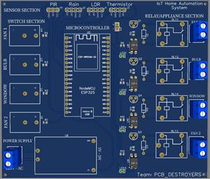
Double Layer Printed Circuit Board (PCB) for Sensors Based IoT Home Automation System
It is a 2 Layer Sensor Based IOT Home autonomation PCB, through which we can control 4 electrical appliances manually or using sensors. It uses ESP32 IOT board as the microcontroller.The PCB is a standalone board with 4 channels to connect home appliances like bulb, fan, Window using 4 different sensors. The board also contain manual switches in case of failure in sensor.
Major Sections in the PCB can be:
i. 5V Regulated Power Supply Section
ii. Readymade Microcontroller Section - ESP
iii. Sensor Section
iv. 4 Channel relay with appropriate drivers, LED indicators & PCB connectors
v. 4 Switches for manual operation.
Working of different parts of PCB:
a. The given circuit is a double layer, sensor-based IoT home automation PCB. It has 4 channels to connect home appliances like bulb, fan, Window using 4 different sensors. The board also contains manual switches in case of failure in sensor.
b. Here we have used a AC-DC (240V AC to 5V DC) convertor for 5V input supply to ESP32, sensors, switches, and relay activation.
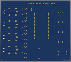
c. This PCB has both SMD (resistors, diode, led, transistor - BC547) as well as THT (Optocoupler - 817C, Relay, MCU, Header pins for Sensors, Connectors, jumper and header for VCC-JDVCC) components.
d. Some of the application of the components used here are:
v BC547 transistors is used for switching purpose.
v 1N4007 protection diode is used to prevent the reverse current caused by stored magnetic energy in relay's inductor as it can cause damage.
v In relay, optocoupler are used, so when the current is passed through internal led of optocoupler the internal photo transistor is activated and it allows current to flow from C->E, which further triggers the main BC547 transistor.
v We give supply to VCC, which is given to JD-VCC via jumper.
We have used 25 mil (1.8 A current) track width for internal signals and 40 mil (2.5 A current) for power signals.


Double Layer Printed Circuit Board (PCB) for Sensors Based IoT Home Automation System


- Comments(0)
- Likes(2)
- 1 USER VOTES
- YOUR VOTE 0.00 0.00

-
8design
-
9usability
-
7creativity
-
7content
More by Abhishek
-
IoT Indoor system with ESP32 to monitor Temperature, Humidity, Pressure, and Air Quality
16 0 0 -
Naruto Multi-color PCB printed with UV technology
59 2 1 -
-
-
-


