


|
|
100nf 0805 Capacitor |
x 11 | |
|
|
100uf 1210 Capacitor |
x 5 | |
|
|
10uf 0805 Capacitor |
x 1 | |
|
|
2.2uf 0805 Capacitor |
x 1 | |
|
|
1N4001 SOD-323 Diode |
x 1 | |
|
|
LED Green 0805 |
x 2 | |
|
|
LED Blue 0805 |
x 2 | |
|
|
LED Red 0805 |
x 2 | |
|
|
LED Yellow 0805 |
x 1 | |
|
|
AON7401 Mosfet |
x 1 | |
|
|
Mini SMD Tact Switch Buton 4 Pin |
x 2 | |
|
|
LM1117 5V Regulator |
x 1 | |
|
|
LM1117 3V3 Regulator |
x 1 | |
|
|
DRV8833 or DRV8848 Motor Driver |
x 1 | |
|
|
AI-Thinker ESP-12F ESP8266MOD |
x 1 | |
|
|
CH340E USB to Serial IC |
x 1 | |
|
|
Type-C USB4105-GF-A |
x 1 | |
|
|
5.1K 0805 Resistor |
x 2 | |
|
|
1K 0805 Resistor |
x 3 | |
|
|
22R 0805 Resistor |
x 4 | |
|
|
0R 0805 Resistor |
x 2 | |
|
|
10K 0805 Resistor |
x 8 | |
|
|
200mR 1206 Resistor |
x 2 | |
|
|
RJ25 6pin Jack Connector |
x 4 |
Open Source Educational Programming Board and Modules (Coded by ChatGPT)
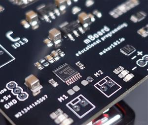
In this project, I will show you the assembly and use of the educational programming board and modules that I designed as open-source. The motherboard is based on ESP8266 WiFi and has four standard RJ25 ports. Ports such as RJ25 are also often preferred on other popular programming boards. This allows the modules to be easily connected to the motherboard and used. In addition, the motherboard enables the control of dual-motor and a servo motor. Finally, all the source codes in the project was created by the very popular ChatGPT recently, with amazing results… Let's get started!
An additional page has been created for the Gerber file of the modules. To order modules, visit this page - https://www.pcbway.com/project/shareproject/Modules_for_Educational_Programming_Board_1a95d540.html

Printed circuit boards are preferred for long-term use, stable and more durable electronic circuit prototypes. I prefer PCBWay to turn my circuit designs into durable prototypes. If you want to have these PCBs with low-price and high-quality, you can get it from the right menu above.
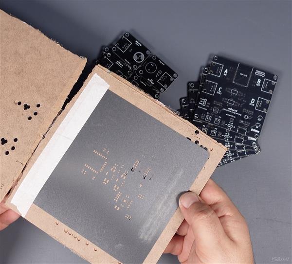
Some "surface mount device" ie SMD components are preferred in this board, this affects the size and cost of the board design. For the assembly of SMD components, a stencil is generally preferred. Solder stencils help to accurately apply solder paste in position of components and the stencil is usually ordered with the PCB. This process is simple, first fix the printed circuit board and place the stencil to match the board. Then put some solder paste on the stencil with the help of a spoon and spread it with a spatula.


After applying the solder paste, it is necessary to place the required components on the PCB. Where to place these components is usually indicated by a designator or footprint reference. These references are used as part of the PCB design and ensure the correct placement of components. Designator shows what a component is and where it is located.


After the components are placed on the solder pads with the help of solder paste, the soldering process begins. Soldering is usually done with a hot plate machine or a hand soldering iron. The soldering machine heats and melts the solder paste and fixes the components in place. After the soldering is complete, the components are completely fixed in place when the solder paste has cooled.


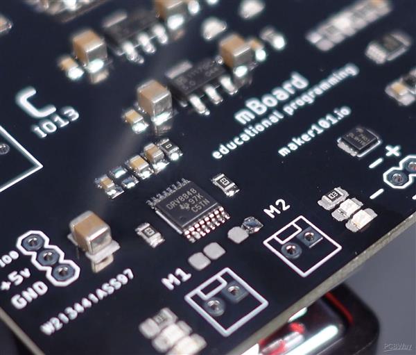
After soldering a few more components, the board will be complete. These components are a few headers and RJ25 jacks. It can be easily soldered with a soldering iron.


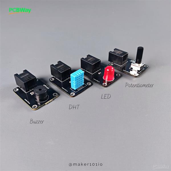
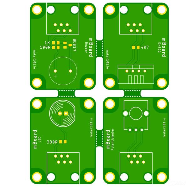
The soldering of the motherboard is complete. At the next stage, there is the soldering process of the modules. The modules are a potentiometer, a humidity and temperature sensor, a buzzer and an LED. It is possible to solder the modules with a soldering iron. For DHT sensor, you can choose version 11 or 22. You can see the locations of the components used in the modules in the shared designator.
By the way, I mixed up the LED and Buzzer module names, but the corrected and updated file has been shared with you. The assembly of the modules is complete, if you have any module add-on suggestions, please share them in the comments.


In this part, grab a cup of coffee and take a closer look at what we can do with ChatGPT! ChatGPT is a popular AI tool, many of you probably know or are using. In the first step I asked ChatGPT to generate a simple Blink code for the LED and Buzzer. Of course, I specified the pins to which the modules will be connected.


The result is quite successful, I copied the generated code and pasted it in the editor. By the way, if you do not have ESP WiFi setup, you will have to complete it by watching the previous project video.

There is a simple thing to do while uploading the code, when you see the "Connecting..." notification, press the boot and reset buttons at the same time, then release the reset and then the boot button. The upload will be completed in a few seconds.

Let's plug the modules into the pins specified in the code and see the result...

As you can see in video, both the motherboard, the modules and the code are working properly.

Now let's test the pot module and the servo motor. What I want from ChatGPT is to generate a code for servo motor control with a pot connected to its analog pin. The result is amazing, added the servo library and used the map function.


Also added the WiFi settings. Since we will not be communicating over WiFi in this project, we are making the settings passive.


Then we upload the code to the board. The result is successful again, the pot module and the servo are working successfully...

The next module is a humidity and temperature sensor. I specified the pin that the module is connected to the board and also the library called DHT to use. I wanted it to generate a code that could display sensor values via serial monitor.


As you can see, the result is again great! Let's upload the generated code to the board and see the values on the serial monitor. The humidity and temperature module also performs its function successfully.

In the final step, let's try to generate code for a DC motor control. The 8848 driver is used for controls the DC motors, so I mentioned this in the question. Next, I defined the pins for the forward and backward motor movements. The driver contains sleep mode and I have specified the pin it is connected to.


Actually the result is fine, but it may have messed up the sleep mode a bit. Perhaps I should add a little more detail to the question. I wrote the details of the sleep mode, and also asked it to use "Pulse Width Modulation" for the motor movements.


This result is really great for DC motor control with pulse width modulation! It will only require a minor change over sleep mode.

Only defining the sleep mode pin as high in the "Setup" section will be sufficient for motor movement. I delete the sleep mode lines defined in the motor movement functions and then the code is ready.

Motor speed values can be defined optionally because "Pulse Width Modulation" is used.

There is the 1117 5Volt regulator on the motherboard, which makes it possible to supply it with an external power source. The motor movement LED indicators on the motherboard are working correctly, so the motor is running successfully.


Thanks for reading! Please like and share for support...

Open Source Educational Programming Board and Modules (Coded by ChatGPT)
*PCBWay community is a shared platform and we are not responsible for any design issues.


- Comments(0)
- Likes(0)
More by MERT KILIC
-
 Robot Sumo Board
Robot-sumo, or pepe-sumo, is a sport in which two robots attempt to push each other out of a circle ...
Robot Sumo Board
Robot-sumo, or pepe-sumo, is a sport in which two robots attempt to push each other out of a circle ...
-
 ESP32 Mecanum Wheels Robot and Bluetooth Gamepad Controller
In this project we will see how to make an ESP32 Mecanum Wheels Robot which is capable of moving in ...
ESP32 Mecanum Wheels Robot and Bluetooth Gamepad Controller
In this project we will see how to make an ESP32 Mecanum Wheels Robot which is capable of moving in ...
-
 DIY Motorized WiFi Roller Blind - ESP8266 & Blynk
In this project we will see how to control a roller blind via a smartphone application. The reason w...
DIY Motorized WiFi Roller Blind - ESP8266 & Blynk
In this project we will see how to control a roller blind via a smartphone application. The reason w...
-
 Pet Feeder Controlled Via WiFi - ESP8266
How It Works?As you can see, a 3D design was used for the pet feeder. ESP8266-based Wemos D1 Mini bo...
Pet Feeder Controlled Via WiFi - ESP8266
How It Works?As you can see, a 3D design was used for the pet feeder. ESP8266-based Wemos D1 Mini bo...
-
 ESP8266 Two Wheel Robot (NodeMCU and Stepper Motor)
Generally, robot cars are built on a chassis with 2 DC motor wheels and a bovine wheel. While surfin...
ESP8266 Two Wheel Robot (NodeMCU and Stepper Motor)
Generally, robot cars are built on a chassis with 2 DC motor wheels and a bovine wheel. While surfin...
-
 3D Printed Rotating Table Board with Arduino Nano and 28BYJ-48 Stepper Motor
This project shows how to make a 3D printed Rotating Table using Arduino and a hobby stepper motor. ...
3D Printed Rotating Table Board with Arduino Nano and 28BYJ-48 Stepper Motor
This project shows how to make a 3D printed Rotating Table using Arduino and a hobby stepper motor. ...
-
 Hand Gesture Controller for Robotic
The hand gesture controller makes it possible to control applicat...
Hand Gesture Controller for Robotic
Hand Gesture Controller for RoboticThe hand gesture controller makes it possible to control applicat...
-
 How To Make DIY Remote Control Hoverboat at Home
In this video, I showed you how to make your own hoverboat from materials available at home and chea...
How To Make DIY Remote Control Hoverboat at Home
In this video, I showed you how to make your own hoverboat from materials available at home and chea...
-
 How to Make DIY Arduino Gesture Control Robot at Home
Parts Required for Receiver (Tank):1) Robot Tank Chassis - https://bit.ly/3j8y2Q52) Arduino Nano V3 ...
How to Make DIY Arduino Gesture Control Robot at Home
Parts Required for Receiver (Tank):1) Robot Tank Chassis - https://bit.ly/3j8y2Q52) Arduino Nano V3 ...
-
 DIY Circuit Activty Board with Paperclips | MAKER | STEM
You can be creative and design your own circuit and add different sensors (other LEDs...). The idea ...
DIY Circuit Activty Board with Paperclips | MAKER | STEM
You can be creative and design your own circuit and add different sensors (other LEDs...). The idea ...
-
 ATtiny85 Wearable Activity Tracking Watch
How to make the wearable activity tracking watch? This is a wearable gadget designed to vibrate when...
ATtiny85 Wearable Activity Tracking Watch
How to make the wearable activity tracking watch? This is a wearable gadget designed to vibrate when...
-
 3D Hollow Clock Controller Board (Arduino Nano, Stepper Motor and ULN2003 Driver)
Hi, in this project I will show you how I made this great-looking 3D-printed Hollow clock. I saw thi...
3D Hollow Clock Controller Board (Arduino Nano, Stepper Motor and ULN2003 Driver)
Hi, in this project I will show you how I made this great-looking 3D-printed Hollow clock. I saw thi...
-
 Explore Simple 3D Dog Robot and Multiple Servo Motor Control Board
Hi there! In this project, you will find 3D part assembly, source code, and Android application of a...
Explore Simple 3D Dog Robot and Multiple Servo Motor Control Board
Hi there! In this project, you will find 3D part assembly, source code, and Android application of a...
-
 Mood Tracker! Get feedback of feelings
What does Mood Tracker do?My daughter started primary school this year, and primary school is challe...
Mood Tracker! Get feedback of feelings
What does Mood Tracker do?My daughter started primary school this year, and primary school is challe...
-
 Make your Hydroponics System fully Automated and view Datas via Dashboard
This project shows how to control the hydroponic system as automation and how to monitor the desired...
Make your Hydroponics System fully Automated and view Datas via Dashboard
This project shows how to control the hydroponic system as automation and how to monitor the desired...
-
 Build a Self Watering System (Soil Moisture Sensor - Water Pump - Water Level Sensor - MOSFET - Circuit - Code)
This project shows how to build a self-watering system whose values can be monitored through an app....
Build a Self Watering System (Soil Moisture Sensor - Water Pump - Water Level Sensor - MOSFET - Circuit - Code)
This project shows how to build a self-watering system whose values can be monitored through an app....
-
 DIY ESP32 Bluetooth GamePad for Android, PlayStation and PC
In this project, we will first see how to build a breadboard gamepad circuit, and how you can commun...
DIY ESP32 Bluetooth GamePad for Android, PlayStation and PC
In this project, we will first see how to build a breadboard gamepad circuit, and how you can commun...
-
 One and Multiple Servo Motor Control With ESP32 Development Board (DOIT ESP32 DEVKIT V1)
IThis article covers controlling a Servo motor using the ESP32 development board. Also, this article...
One and Multiple Servo Motor Control With ESP32 Development Board (DOIT ESP32 DEVKIT V1)
IThis article covers controlling a Servo motor using the ESP32 development board. Also, this article...
-
Naruto Multi-color PCB printed with UV technology
56 2 1 -
-
-
-
-
Open Source Very Large Stick - Freejoy & MMjoy2 breakout board
685 0 0


