


|
KiCADKicad
|
Atmega32U4 Customize Mini-development Board
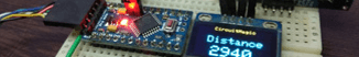
The objective of your development board can be directly reflected in its layout. The photo shows a development board that was utilized to regulate the rotational speed of a DC motor. The computer's serial port managed the DC motor's operation. When troubleshooting was required, the LEDs came in handy. To demonstrate how to construct a flexible development board, I will not use the same components depicted in the accompanying image throughout this instruction.
Step 1: Components
The components needed for the project include an ATmega88 microcontroller, various resistors, capacitors, LED, jumpers, and a stripboard. For programming, an ISP programmer like AVRISP mkII is recommended, or an Arduino board can be configured as an ISP programmer.
Step 2: Datasheet
Use the ATmega88 datasheet for essential details to build and program a development board—attention to specific pin functionalities, such as reset, Vcc connections, and programming pins.
Step 3: Circuit Drawing
Use KiCAD to create the circuit diagram. It may seem complex initially, but experimenting with its features will make it effective. Utilize 'A' for component search and 'Double right-click your mouse' for placement. For easy and quick learning about KiCAD watch this video. Your circuit should be like the one below.

Step 4: Reset Pin Pull-up
Adding a manual reset option for the microcontroller is beneficial. You can achieve this by connecting a SIL2 in line with a 100-ohm resistor to the ground. By short-circuiting the SIL2 with a jumper, the microcontroller will reset. The 100-ohm resistor ensures that the capacitor does not get short-circuited. To proceed, refer to the circuit diagram provided in the document.
The pull-up connection is demonstrated in the KiCAD circuit above.
Step 5: Power Supply
The board uses 10 μF capacitors near the voltage input and 0.1 μF capacitors between specific pins as low-pass filters to prevent interference. Users can add a voltage regulator like 78L05 for battery operation.
Step 6: ISP Programmer
ISP programmers are needed to program processors. 6–10-pin connectors are available. My arrangement uses a 6-pin connector. Design the connection using the hardware document. ISP-programmer means In-System Programming. Using this programmer style eliminates the need to install the chip individually before integrating it into the system. After installation, reprogramming is easy.
Step 7: Design
The development board can control coffee machines.
A development board power LED speeds debugging.
Develop a board:
- Print and cut the circuit schematic.
- Make a paper-sized stripboard.
- Align the paper holes over the stripboard and glue it to the side without copper strips using an ordinary glue stick.
- Assemble red crosses.
- Solder components from bottom to top. This simplifies assembly.
- Program the development board with 5V.
Congratulation on completing a development board hardware design!

Step 8: Programming
Use Atmel Studio C to create amazing creations with your unique development board by downloading the app. C samples teach Arduino's language better than boot-loading. Timers, interrupts, and analog reading improve. The ATmega88 datasheet includes example codes for your microcontroller's unique tasks.

PCB Prototype the Easy Way
I decided to order for manufacturing of this product through PCBway and the process was very successful. Some of the benefits that made me enjoy include fabrication and assembly under a single roof, quality assurance, an online quoting system, instant quotes, expert DFM feedback, real-time production tracking, fair prices, manufacturing data at your fingertip, and on-time shipping. Their services are recommendable. To order, visit their PCB Instant Quote page and enjoy.
Atmega32U4 Customize Mini-development Board
*PCBWay community is a shared platform and we are not responsible for any design issues.


- Comments(0)
- Likes(1)
More by Simon Mugo
-
 High Power Three Channel LED Driver
IntroductionI have been thinking about how to drive RGB LED patterns most simply. In my day-to-day r...
High Power Three Channel LED Driver
IntroductionI have been thinking about how to drive RGB LED patterns most simply. In my day-to-day r...
-
 433 MHz Radio Frequency Transmitter Module
IntroductionTwo devices can communicate with each other using radio frequencies and using an RF tran...
433 MHz Radio Frequency Transmitter Module
IntroductionTwo devices can communicate with each other using radio frequencies and using an RF tran...
-
 Customized Servo Motor Driver Board
IntroductionServo motors, also called rotary or linear actuators, are designed for minimal control o...
Customized Servo Motor Driver Board
IntroductionServo motors, also called rotary or linear actuators, are designed for minimal control o...
-
 Arduino Customized L298M Dual Motor Driver Module
IntroductionThe Arduino Customized L298M Dual Motor Driver Module is designed to handle high-power D...
Arduino Customized L298M Dual Motor Driver Module
IntroductionThe Arduino Customized L298M Dual Motor Driver Module is designed to handle high-power D...
-
 Overvoltage Protection Board
PrecautionBefore making use of the circuit in this design project, ensure that you first set the var...
Overvoltage Protection Board
PrecautionBefore making use of the circuit in this design project, ensure that you first set the var...
-
 Automatic Residential Lighting System Board Based on AT89C51
In our day-to-day activities, we often don't remember to switch off or on the lights in our rooms. T...
Automatic Residential Lighting System Board Based on AT89C51
In our day-to-day activities, we often don't remember to switch off or on the lights in our rooms. T...
-
 The Energy Saving Bulb Board
The traditional incandescent bulb is an energy waster and it should be removed off shelves. My new t...
The Energy Saving Bulb Board
The traditional incandescent bulb is an energy waster and it should be removed off shelves. My new t...
-
 ESP8266 MINI TEST BOARD
Design Of The SchematicThe schematic design is done in KiCAD. The process starts with finding the da...
ESP8266 MINI TEST BOARD
Design Of The SchematicThe schematic design is done in KiCAD. The process starts with finding the da...
-
 POWER SUPPLY FOR THE ESP8266
ESP8266 is a microchip of low cost that is produced by a company by the name of ESPPRESSIF stems. It...
POWER SUPPLY FOR THE ESP8266
ESP8266 is a microchip of low cost that is produced by a company by the name of ESPPRESSIF stems. It...
-
 TSL25911 Light Sensor
IntroductionWe interact with different intensities and strengths of light in our daily activities. T...
TSL25911 Light Sensor
IntroductionWe interact with different intensities and strengths of light in our daily activities. T...
-
 SIM800 GPS module
ElevatorThis project demonstrates how you can develop various GPS/ GPRS and SMS capability developme...
SIM800 GPS module
ElevatorThis project demonstrates how you can develop various GPS/ GPRS and SMS capability developme...
-
 nRF51822 Mini Evaluation Board
IntroductionDemand for development and evaluation boards the world over has increased. Due to such d...
nRF51822 Mini Evaluation Board
IntroductionDemand for development and evaluation boards the world over has increased. Due to such d...
-
 Customized LM393D Soil Moisture Sensor Board
ElevatorThe project is good at converting analog signals from the soil to digital signals for soil m...
Customized LM393D Soil Moisture Sensor Board
ElevatorThe project is good at converting analog signals from the soil to digital signals for soil m...
-
 PAM8403 Amplifier Module
IntroductionThis is a simple project for improving your musical or audio entertainment by powering y...
PAM8403 Amplifier Module
IntroductionThis is a simple project for improving your musical or audio entertainment by powering y...
-
 741 IC Bass Booster
IntroductionIn this project, we are going to design a bass booster circuit using the 741 IC. This is...
741 IC Bass Booster
IntroductionIn this project, we are going to design a bass booster circuit using the 741 IC. This is...
-
 LM317 AND LM337 ADJUSTABLE POWER SUPPLY CIRCUIT BOARD
IntroductionThe LM317/LM337 symmetrical power supply circuit is an electronic setup for meeting the ...
LM317 AND LM337 ADJUSTABLE POWER SUPPLY CIRCUIT BOARD
IntroductionThe LM317/LM337 symmetrical power supply circuit is an electronic setup for meeting the ...
-
 230V AC to 1.5V DC PCB for Your Application
IntroductionA power management integrated circuit (PMIC) is utilized to supply the necessary power t...
230V AC to 1.5V DC PCB for Your Application
IntroductionA power management integrated circuit (PMIC) is utilized to supply the necessary power t...
-
 Magnetic Polarity Sensor
IntroductionThe north pole and south pole are the only existing polarities when it comes to a magnet...
Magnetic Polarity Sensor
IntroductionThe north pole and south pole are the only existing polarities when it comes to a magnet...
-
Open Source Very Large Stick - Freejoy & MMjoy2 breakout board
496 0 0 -
RF Control training board for students based on ESP32 C3
666 0 2 -
-
KINETIC COASTERS with a TWIST! Laser or 3D Print some DIY Magic
601 0 1 -
RPI - 8 IO PLC With ATTiny85 Watch Dog
527 0 1 -
Nintendo Famicom HVC-001 Controller Shells
622 0 1 -
COMMODORE 128 DIAGNOSTIC REV.785260 KEYBOARD DONGLE
585 0 4 -
COMMODORE 128 15KHz DISPLAY ADAPTER (C128 80 COLUMN ADAPTER)
793 1 6 -


