This tutorial takes a 1mm through-hole and a 1.6mm pad as an example.
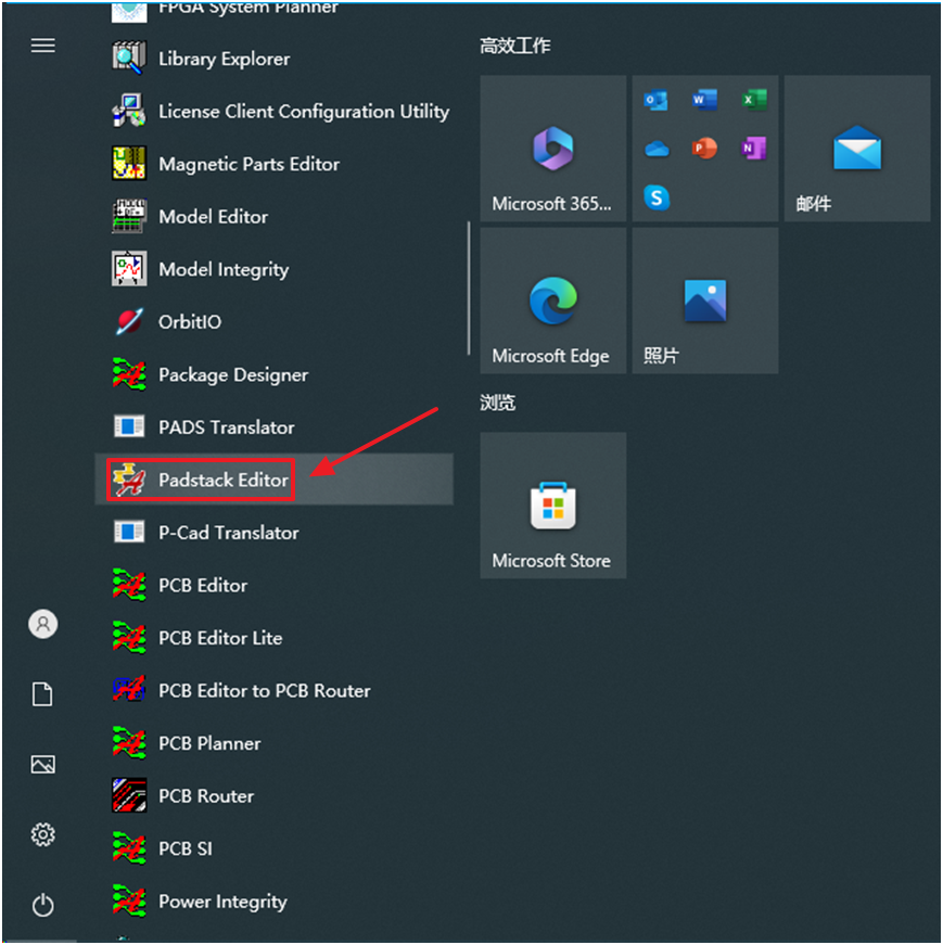
Step 1: Find Padstack Editor and then click.
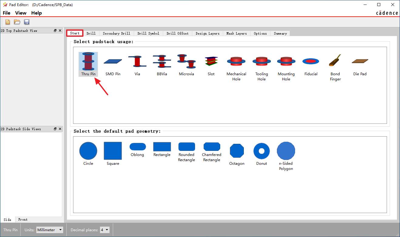
Step 2: Select Thru Pin on Start interface.
Step 3: Switch to Drill interface and fill out Hole type, Finished diameter and Hole plating.
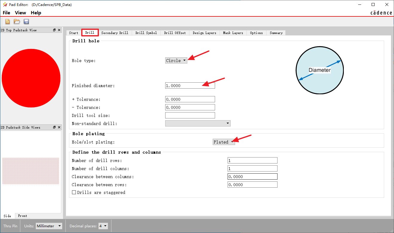
Note: Here we introduce plated through-holes, so "Plated" is selected for Hole plating. If you want to create non-plated through-holes, please select "Non-Plated".
Step 4: Switch to Drill Symbol interface and fill out the drill symbol information.
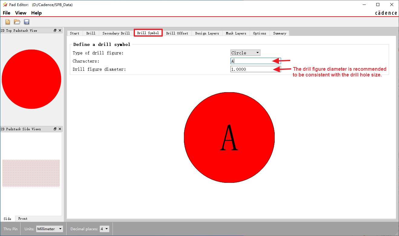
Note: Drilling symbols can be filled out or not. Before the output of light drawing on the PCB in the later stage of design, the drilling symbols can be automatically assigned by updating the drilling symbols through the software.
Step 5: Switch to Design Layers interface and set the pad size.
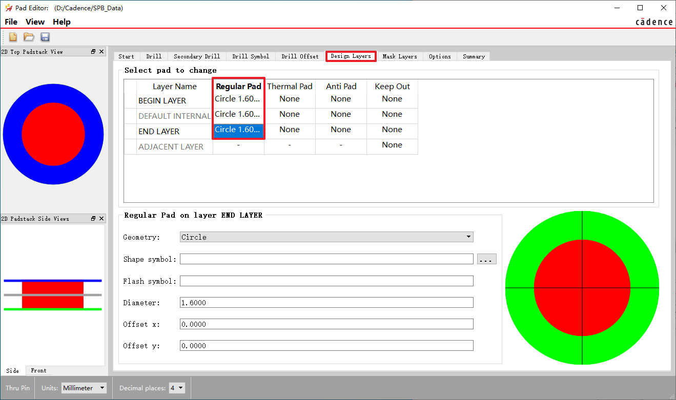
Note: If your design is a negative film design, then it is necessary to define Thermal Pad and Anti Pad.
Step 6: Switch to Mask Layers interface and set SOLDERMASK_TOP和SOLDERMASK_BOTTOM parameter.
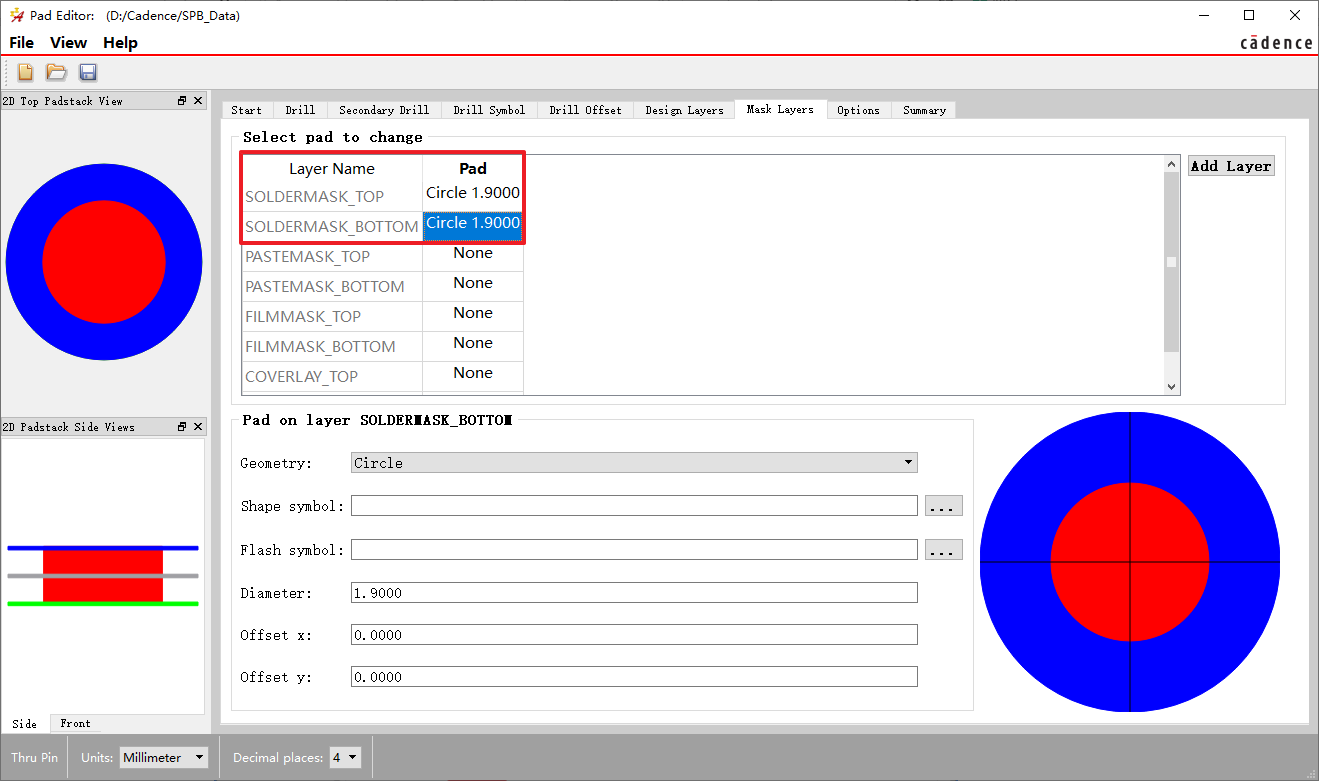
Note: In general, through-hole pads do not need to define PASTEMASK, except for through-hole devices that require reflow soldering.
Step 7: Switch to Options interface. Select the options as the figure below shows:
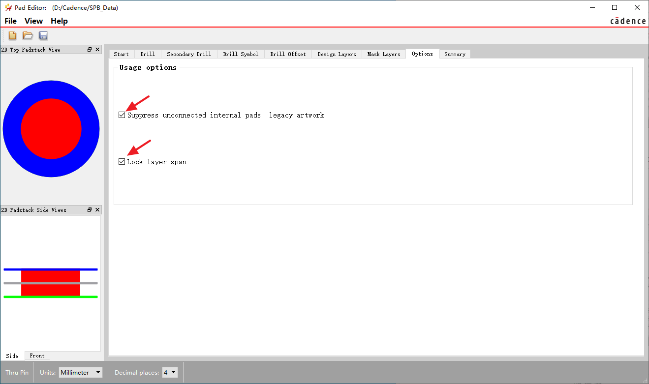
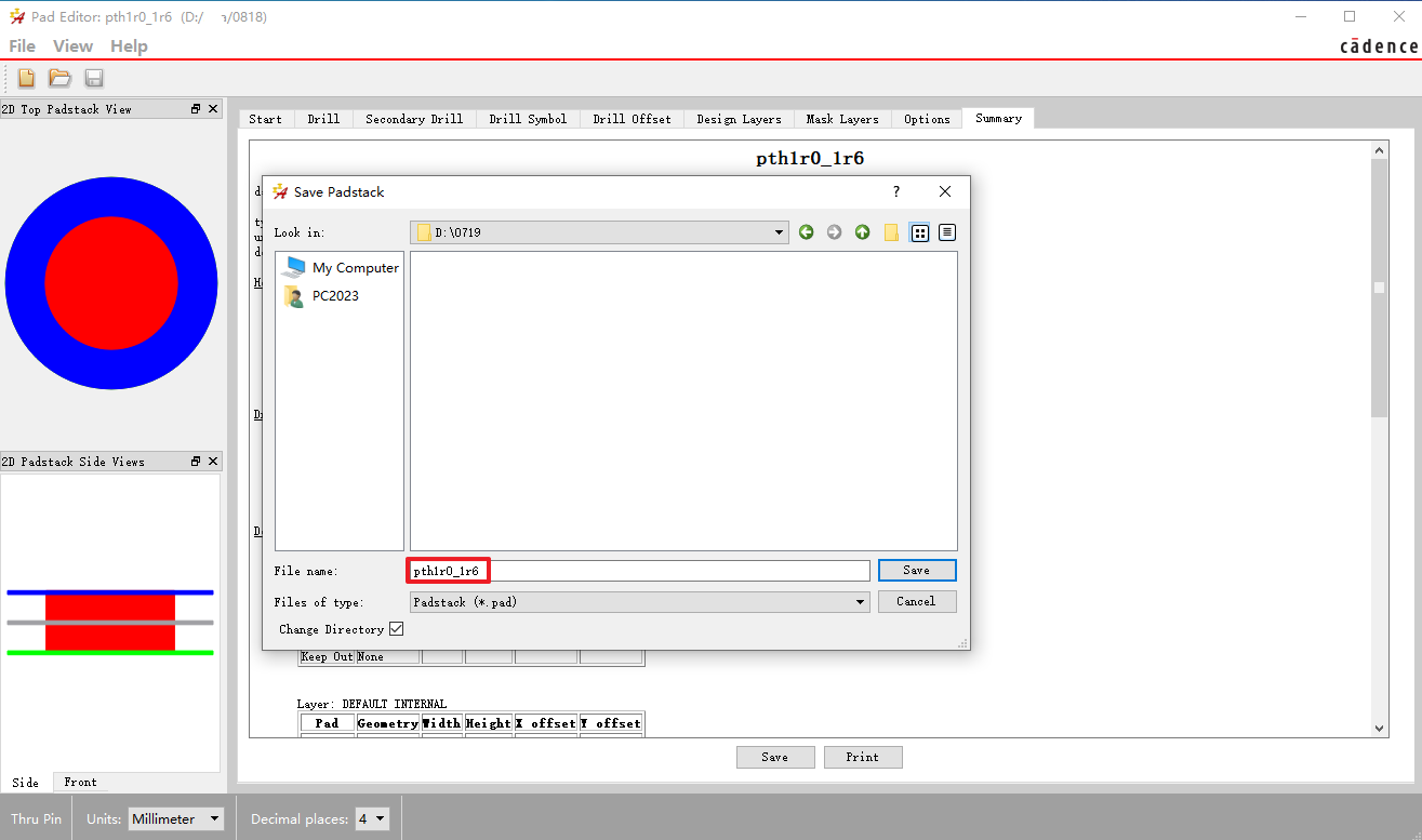
At this point the pad has been completed, select "File"->"Save As" to save the file.

We name this through-hole pad PTH1R0_1R6, and you can name it according to your company's package naming standards.