Summary: In this article, I repair a 1983 Commodore 2031-LP 5.25″ FDD with the aid of some 23XX-to-27XX EPROM adapter PCBs that I bought through PCBWay!
I recently acquired my first Commodore 2031-LP 5.25″ FDD, another vintage disk drive to add to my collection, and a rather uncommon one at that. The drive was in reasonable condition and came with several accessories, however it was bought untested and sold-as-seen after being stored at the bottom of a wardrobe for several decades.
The Commodore 2031 and Commodore 2031-LP are single-unit 5.25″ FDDs, which use the parallel IEEE-488 interface common to Commodore PET/CBM computers. Essentially, both models are a single-drive version of the CBM 2040/4040 units. Where the 2031 has a similar steel case to the CBM 9060/9090 HDDs, the 2031-LP uses the lower-profile tan case of the the Commodore 1540 FDD as intended for home computer use.
The Commodore 2031-LP was sold between mid 1981 and late 1983, at which point it was discontinued – these were not very popular drives in comparison to the “home” equivalents (such as the 1541) as they were only directly compatible with the PET series of computers which were not as common themselves (PETs were primarily sold for educational use, rather than home use), so are quite difficult to find and fetch quite strong prices.


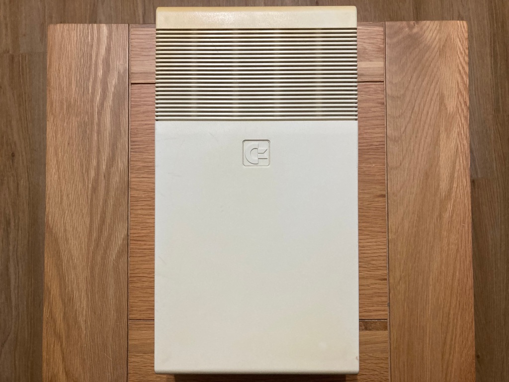
Commodore 2031-LP 5.25″ FDD before restoration.
The drive was “sold-as-seen” for spares/repairs – the previous owner had inherited the drive and has no means of properly testing it, and although they did try powering it up, they weren’t sure it was doing exactly what it should do.
The drive seemed to be completely original, with an early long mainboard (similar to that from a Commodore 1540 or early VIC-1541), and both original ROMs.
The early long mainboard does not have a dedicated motor controller IC (MOS 325572-01), and its functionality is instead implemented using discrete logic ICs; however, unlike the Commodore 1540 which has four 2114 SRAM ICs (for 2KB RAM), the 2031-LP mainboard instead uses a single 6116-type SRAM IC.


Commodore 2031-LP interior before restoration.
The Commodore 5.25″ line of FDDs are, effectively, computers in their own right – they have their own 8-bit CPU (usually a 6502 running at 1MHz, the same as in the VIC-20 computer), their own ROM (usually 16KB) with their own operating system (CBM DOS), their own RAM (usually 2KB), and their own I/O control (usually two 6522 VIAs, the same as the VIC-20 computer). This makes them large, heavy, and expensive – many cost more than their counterpart computer did back in the day, meaning that they were often out-of-reach for the average user and, as such, they were not very popular in Europe.
Unlike the Commodore 1540/1541 series of 5.25″ FDDs which use a serial IEEE-488 (IEC) bus clocked at 2,400 baud by default (approx. 400 bytes per second), the Commodore 2031-LP uses a standard parallel IEEE-488 (GPIB) bus which is capable of significantly higher transfer speeds (approx. 2,100 bytes per second).
But, I digress – back to the restoration.
Drive diagnosis and repair

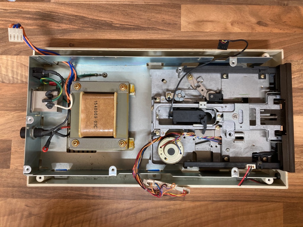
Drive mainboard and chassis following initial cleaning.
The drive interior was filthy, so I cleaned it up for a proper inspection before initial testing. Eagle-eyed viewers may already spot a problem in the first picture.
I powered up the drive for the first time, and as shown in this video, it wouldn’t boot up properly. When powered on, the green power LED should stay on, the spindle motor should run for a short time then stop, and the red activity LED should go on for a short time (approx. two seconds) the go off. Instead, the green power LED would come on and stay on, however the spindle motor would run continuously, and the red activity LED would flash very briefly (approx. half a second).
This was not an expected failure mode behaviour documented in the 2031/2031-LP service manual, so it was time for some further investigation.

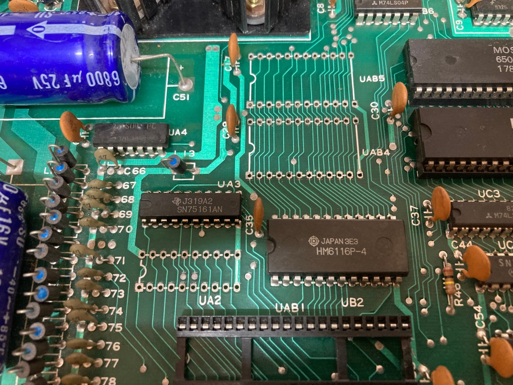
SN75160AN IC (UA2) with its very unnerving burn mark on top.
From an initial inspection, the ROM socket at UAB4 had minor corrosion, and the SN75160AN IC at UA2 (which is used alongside the SN75161AN at UA3 for interfacing over the parallel bus) seemed to have blown its lid at some point in the past.
This could have been caused by a failure of the IC itself, by some kind of short on the bus causing overcurrent, or by overvoltage from the internal power supply.
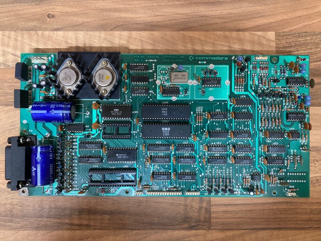

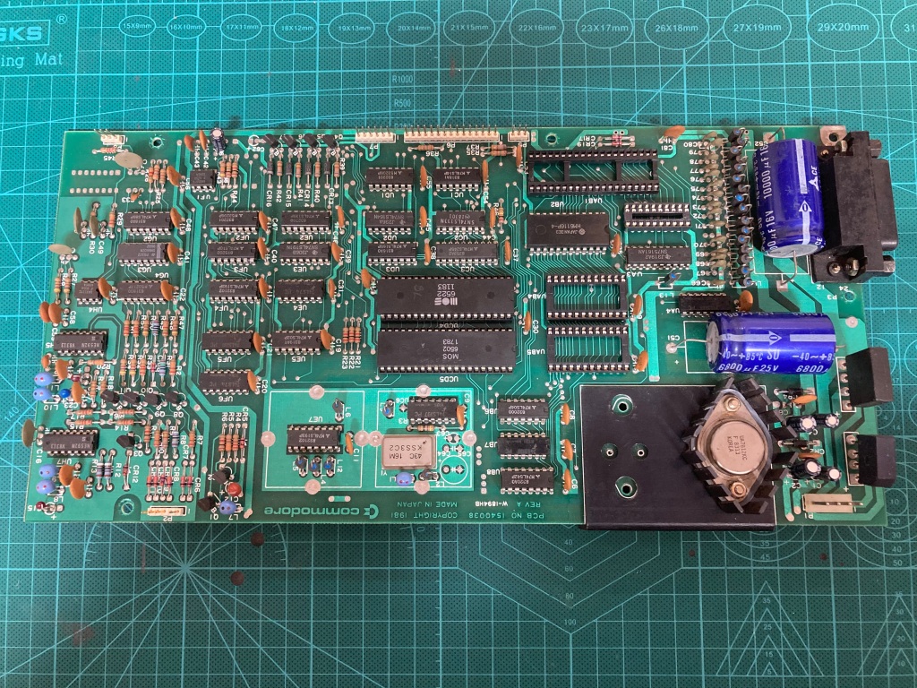
Mainboard front and rear before restoration.
The first thing I did was therefore to remove the original ROM socket at UAB4 and the failed SN75160AN IC at UA2 using my desoldering station (a Duratool D00672) – these boards have nice big via pads, so are quite easy to work on. I also removed the soldered HI ROM at UAB5 for testing, as MOS mask ROMs of this era are notoriously unreliable.

UAB5, UA2, and UAB4 socket removed.
UAB4 socket and UA2 damage.
I then installed sockets on UAB4, UAB5, and UA2 – these allow for the easy removal and installation of ICs without soldering, and I like to install them whenever I have removed an IC as they are cheap and remove the need for future rework.
I always use high-quality double-sided sockets, which are more reliable than cheap single-sided sockets as they contact the IC legs on both sides – a lot of people push the use of turned-pin sockets, but I don’t like using them as they make swapping ICs difficult, they are difficult to desolder, and they are visibly obviously non-standard.


Mainboard with sockets installed.
With the damaged IC at UA2 removed and the original ROMs reinstalled, I tried testing the drive again, but there was no change in symptoms.
After being left switched on for a couple of minutes, the red activity LED would start to stay on constantly, and the spindle motor would stop and start itself continuously as though the drive was resetting itself. This hinted to some form of power issue.
Commodore 1541-type drives have an internal power supply which produces two regulated outputs, +5Vdc and +12Vdc, each with their own TO-3 linear regulator. I tested the voltage rails with my multimeter – the 12Vdc rail was sitting stably around 12.0Vdc, however the 5Vdc rail was reading around +5.2Vdc (which is on the high side) when cold which seemed to increase as the drive warmed up. Not good!
This most likely indicated a faulty 5V regulator, which was an older Fairchild part (SH323SC), unlike the 12V regulator which was a later Fairchild part (UA7812KC).

TO-3 package 5V regulator removed.
I removed the original 5V regulator, and replaced it with a spare part (a later Fairchild UA7805KC) from an irreparable 1541 mainboard. These are fairly easy to remove – they have two soldered pins, and are held in place with two small bolts. If you are replacing one of these regulators yourself, be careful to reinstall the insulating mica spacer that sits between the regulator and the heatsink, and be careful to reinstall the insulating plastic sleeving over the two bolts – these stop the regulator from shorting onto the heatsink.


Mainboard with replacement 5V regulator installed.
With the replacement regulator installed, the 5Vdc rail was sat at a steady 5.0Vdc – the red activity LED now stayed on constantly and the spindle motor ran continuously, as shown in this video. There was obviously still problems, but it was progress nonetheless.

Drive behaviour with replacement 5V regulator.
I noticed that the DOS 2.6 HI ROM (MOS 901484-03) got noticeably hot quite quickly when the drive was powered up. This era of MOS mask ROMs are notoriously unreliable, but 2031-LP ROMs are difficult to come by, so I didn’t have any spares to try out or a known-good drive to test the suspect ROM in.
Unfortunately, the 2031-LP uses 8Kb (1KB) 2364 ROMs (see below), which are a deprecated standard – these aren’t directly supported by my TL866-II EPROM programmer so I wasn’t easily able to read and verify the suspect ROM, and it’s difficult to get hold of 2364 EPROMs so making up a plug-and-play replacement would not be easy either.

Common Commodore ROM types (image credit: 64Copy Central).
27XX (28-pin) EPROMs are still readily available, are supported (read/write) by the TL866-II, and can be adapted for use in place of 23XX (24-pin) ROMs.
The first hurdle was to build a 2364 to 2764 adapter, to allow the suspect MOS 901484-03 to be read and verified against the corresponding factory binary file.

2364 to 2764 ROM adapter pinout (image credit: 64Copy Central).
There are several guides available on the internet of how adapters can be made up – I followed this one, which shows how to fit a 28-pin 2764 EPROM into a 24-pin 2364 ROM socket, but in reverse – as such, I ended up with a 24-pin socket wired into a 28-pin socket.
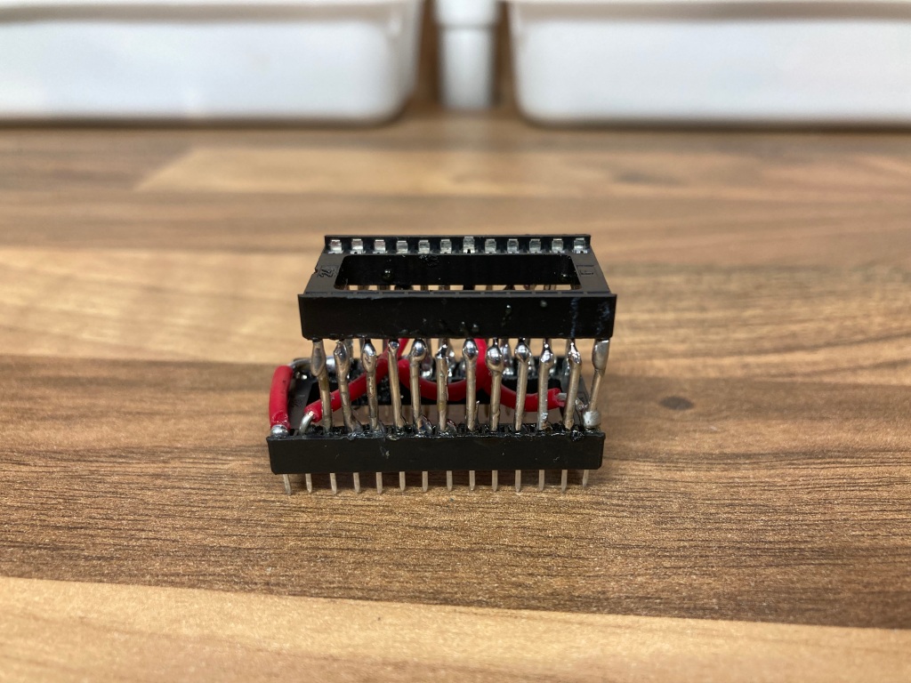 2364 to 2764 ROM adapter assembled.
To make sure that everything was connected up properly, I tested this adapter by reading out a Commodore 64 Kernal ROM (which is also an 8Kb 2364 mask ROM) – as you can see below, this worked fine.
 Commodore 64 Kernal ROM read and verified.
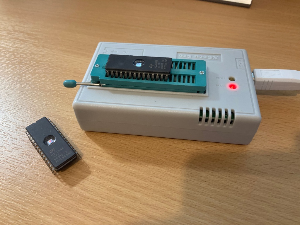
 ROMs being read using the 2364 to 2764 adapter.
I tried reading the suspect ROM (MOS 901484-03), and it wouldn’t read at all. Not good! This chip seems to have failed.

MOS 901484-03 fails to read.
I tried reading the other ROM (MOS 901484-05), and it read fine – I also correctly verified its contents against the corresponding factory binary file using HexCmp2.


MOS 901484-05 reads and verifies correctly.
So, the MOS 901484-03 ROM needed to be replaced.
Burning a replacement 2764 EPROM
For testing, I bought some 2764 EPROMs on AliExpress – these appeared to be rebranded parts (i.e. branded ST but actually AMD parts according to the chip ID), but they seem to be genuine 2764 EPROMs and they work fine.
First of all, I erased some of the 2764 EPROMs using a UV EPROM eraser. Unlike EEPROMs which are electrically-erasable, EPROMs (which have cute little windows on top of them) need to be erased prior to programming using UV light.
 EPROMs and UV eraser.
Then, I programmed up one of the pre-erased 2764 EPROMs using the factory binary file for the MOS 901484-03 (DOS 2.6 LO).
 EPROMs during programming.


2764 EPROM programmed correctly.
I then read back and verified the ROM contents using HexCmp2.
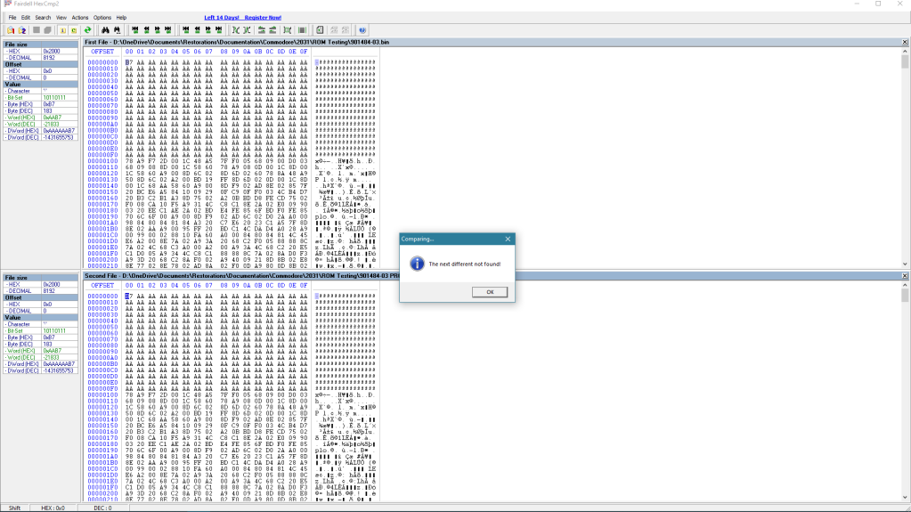 MOS 901484-03 reads and verifies correctly.
I then printed and attached a label to cover the erase window.
Making a 2764 EPROM to 2364 ROM adapter
At the time of me doing this repair, a limited number of sellers were selling 27XX to 23XX ROM adapters but none of these were in the UK, so I decided to make some of my own. There are now some more options available, including on eBay
In a similar manner to the 2364-2764 adapter that I made up for reading the suspect ROM, it would also be possible to just solder together another 24-pin and 28-pin socket and call it a day. However, this was very fiddly and took a long time, and it looks a bit of a mess, so I wanted a more professional solution.
I managed to find an open-source PCB design for a very versatile 27XX to 23XX ROM adapter, available on the PCBWay Shared Projects page. I decided to order a set of these PCBs through PCBWay because of how easy it is to order their shared project PCBs and because of their excellent prices (10 PCBs for $5.00 + P&P, a percentage of which is paid to the project author), and I had a very good experience overall.
 27XX to 23XX ROM adapter (image credit: SukkoPera’s GitHub).
The adapter is very well documented, and is suitable for use with either 2764 (1Kb), 27128 (2Kb), 27256 (4Kb), and 27512 (8Kb) EPROMs/EEPROMs by setting three jumpers using 0805 SMD resistors (either 0R or 10k). Larger ROMs can contain multiple images, which can be switched between using the pads exposed on the edge of the adapter.

27XX to 23XX ROM adapter jumper settings (image credit: SukkoPera’s GitHub).
Aside from the PCBs, a handful of components are required – per adapter, this includes:
 ROM adapter PCB and components.
These adapters are really easy to assemble: first, the pin headers are cut down to size then soldered into the 24-pin footprint facing away from the underside of the PCB (the side with the resistor pads), taking care to ensure that they are installed straight (by using a breadboard to hold them in place, for example); then, the solder joints on these can be snipped down, and the 28-pin socket installed on the top-side of the PCB; finally, the resistors R1-R3 can be fitted as required.
In this case, as I was replacing a 2364 mask ROM with a 2764 EPROM, I just installed wire bridges across R1, R2, and R3, as these address lines are not used.


ROM adapter PCB assembled and ready for installation.
I assembled an adapter to test with, then installed it into the drive.


ROM adapter and EPROM installed into the drive.
Unfortunately, there was no change in symptoms, so this drive had even more problems.
Drive diagnosis and repair (continued)
To summarise, even with a faulty SN75160AN IC removed, a new ROM and socket fitted at UAB4, a known-good ROM fitted at UAB5, and a new 5V regulator installed, the drive was still not booting up correctly – the red activity LED still stayed constantly lit, and the spindle motor still ran continuously.
This behaviour is documented as a known failure mode in the 2031/2031-LP service manual, which recommends to check the 6502 CPU and 6522 VIAs.
All of these ICs were socketed on this board, so were easy enough to test in a known-good 1541 drive – the 6502 CPU (UCD5) tested OK, however the 1541 exhibited the same behaviour as the 2031-LP whenever either of the 6522 VIAs were installed, so both had failed.
Before doing any work on the drive initially (when the 75160AN IC was still installed), I noticed that the 6522 VIA at UAB1 got very hot – I swapped the two VIAs over to check whether the symptoms changed, but the other VIA also got very hot when fitted at the UAB1 position (most likely due to the failed 75160AN IC being shorted).
It’s therefore possible that previously only the UAB1 6522 VIA was faulty, and that I killed the other 6522 VIA from UCD4 when I swapped it into the UAB1 position with the failed 75160AN IC still fitted. Oh well! These things happen.
I fitted two replacement 6522 VIA ICs (both salvaged from a VIC-20), and the drive booted up normally – the red activity LED would light up for a brief period (approx. two seconds), and the spindle motor would run for a brief period (approx. two seconds). Fantastic!
 Drive mainboard with replacement 6522 VIAs fitted.
Out of interest, I re-fitted the original DOS 2.6 LO mask ROM (MOS 901484-03) to see what kind of symptoms this would give, and the drive wouldn’t boot, so the ROM was definitely bad – the spindle motor would run continuously and the red activity LED would give a flash code, indicating an inaccessible ROM.
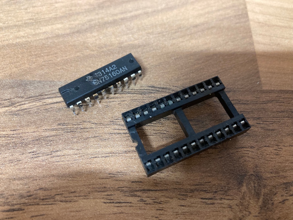
I then installed a new-old-stock SN75160AN IC at UA2, and the drive still booted OK.
So, in total the faulty parts were: an SN75160AN IC, which had went up in smoke; a 5V regulator, which had stopped regulating; two 6522 VIAs, which had stopped interfacing; a MOS 901484-03 mask ROM, which had stopped reading.
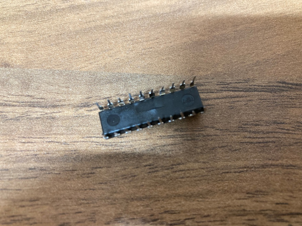
 Faulty parts.
Case restoration
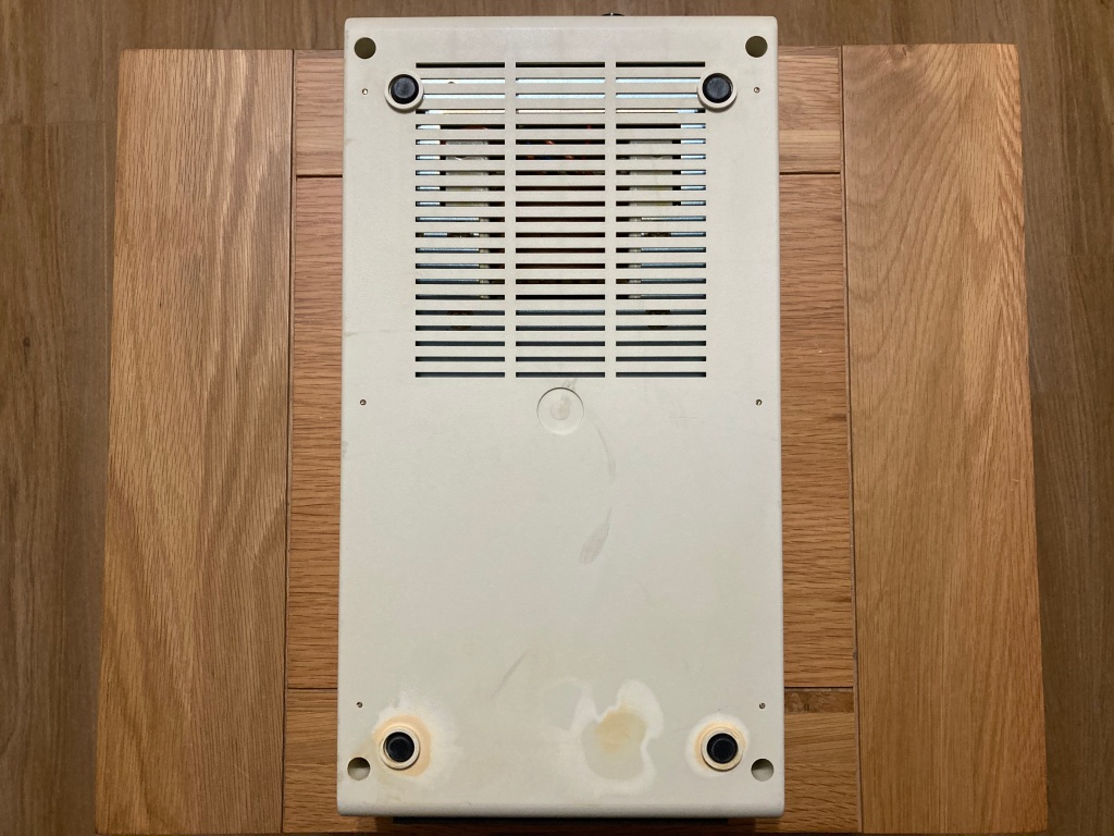
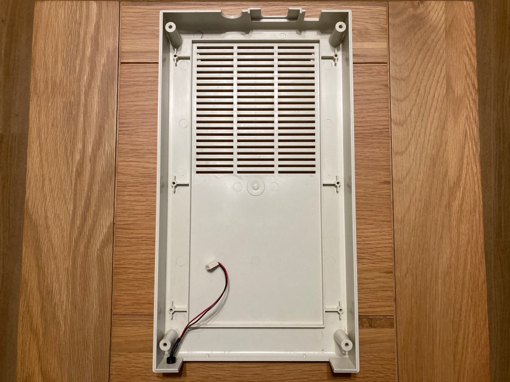
The case was in reasonable overall condition, and was rather yellowed – the upper case was in good condition, however the lower case seemed to have irreparable chemical damage, so would have to be replaced.
I managed to source a replacement lower case from another cream 1541-style drive – the 2031-LP shares its case colour and design with the 1540 and VIC-1541.
I decided to try treating the yellowing on the upper case, but instead of mucking about with hydrogen peroxide like I have in the past (which is unreliable and a lot of effort), I decided to try “sunbrighting”.
 Drive upper case being bleached in the sun.
The weather was rather nice at the time of this repair, and sure enough a few days in the glorious sunshine reduced the overall yellowing very significantly with no chemicals – the yellowing was worst in patches on the front and rear of the drive, so I concentrated on these. As you can see from the pictures, there is still a patch of yellowing at the rear of the drive, but this is not visible during normal use and it is 90% better than it was before.


Drive part-way through the sunbrighting process.
Testing and finishing up
I took this opportunity to clean all of the IC sockets and rear ports on the mainboard using contact cleaner, clean the read/write head and stepper rails on the mechanism using cotton buds and 99.9% IPA, and lubricate the stepper rails and disk mount using lithium grease.
In this case, the head rails were extremely sticky, so I cleaned and lubricated them, then gently worked the head up and down the rails to free it up.


Drive chassis and mainboard reinstalled.
For testing, I bought a reproduction 2031 demo disk from MicroMate on eBay.


Reproduction 2031 demo disk.
I connected the drive up to my PET 3032 which uses the same IEEE-488 parallel interface, then tried loading a directory – happily, the drive seemed to work!
 Commodore 2031-LP and PET 3032.
The factory demo disk that came with all Commodore disk drives contains a performance test utility, which exercises the functionality of the drive and can be used to verify that the drive is working correctly. In this case, all tests passed.

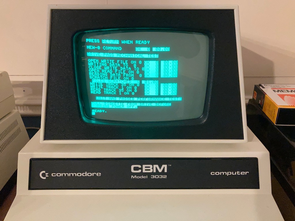
Drive passes performance test on demo disk.
After all this work was performed, I did some finishing up: I thoroughly cleaned the mainboard with compressed air and an ESD-safe brush; I thoroughly cleaned the case inside and out using Cillit Bang general-purpose degreaser, a microfibre cloth for large areas, and a toothbrush for small areas.
The drive seemed to work OK, but thorough testing is necessary to verify correct operation, so I did as much testing as I could.
Another restoration complete, and another Commodore disk drive saved!


Commodore 2031-LP 5.25″ FDD following restoration.
Review of PCBWay
I’m quite new to ordering custom PCBs (as a hobbyist, at least), so I thought I’d write a quick review of PCBWay to help out other new starters. These are the third set of PCBs that I’ve ordered from PCBWay and I’ll definitely be buying more in the near future – I’d eventually even like to work my way up to developing my own circuit designs and layouts.
The minimum order quantity for these small PCBs was 5, at $5.00 per set, and 10 PCBs were also $5.00 (bargain!). You can claim your $5.00 new user voucher here, if you so wish.
When you add a design (or designs) to your online shopping cart, they will go through a short review process by your assigned sales rep. In my case, this took less than an hour.
Once you’ve placed your order, you are taken to a detailed order manufacturing screen, where you can track the process through each exact manufacturing step. I chose a 24-hour build time for this project, which was standard at no extra cost, and my boards were shipped the next working day.
Shipping via DHL (2-4 working days) between China and the UK cost around £20.00 for this order, and the parts arrived safely and extremely quickly. There are cheaper shipping options available (i.e. China Post), but these will take significantly longer to arrive, and there are medium-cost options (including PCBWay's own shipping service) which are a compromise between delivery time and cost.
For this order, I wasn’t subject to any import charges, but this may apply to orders of greater value – these are the responsibility of the buyer, and will be paid following delivery.
My order was well packed, and the PCBs are of a very good quality, and work exactly as intended! PCBWay’s communication and service throughout the process was also very good, and I’m very pleased with my experience overall.
The PCBWay Shared Projects page is extremely useful for quick prototyping, or for those like myself who don’t currently have any of their own designs. Its integration with the ordering process is seamless, so it’s very easy for hobbyists to get boards made. Shared project authors also get paid for their work when you buy.
There are lots of shared projects available for vintage computing enthusiasts in particular, and PCBWay seems to have a good standing in the community. If anyone has a project that they would like to share on the PCBWay page, they can do so here.
I hope this helps any PCB newbies like myself! If you have any questions, let me know and I’ll try to help out if I can.
For more vintage computer related content, check out my website!
Original post on my website here.


